Get in Touch with Saiweiglass


BK7 Optical Glass: Properties, Applications, and Limits

Updated October 2026
BK7 is a borosilicate crown glass, found in lenses, prisms, and optical windows. Understanding BK7 optical glass properties and applications begins with the light path: how much useful light reaches the detector depends on the wavelength, glass thickness, and surface finishes. SCHOTT N-BK7 provides a named reference grade for the values shown below.
For visible imaging and other instrument windows, this material is a good starting point. Near the ultraviolet or infrared limits, a sample may appear clear and transparent, but it can absorb more light than its appearance suggests. Begin with spectral data, then decide what surface and material tolerances the instrument actually needs.
What Is BK7 Optical Glass?
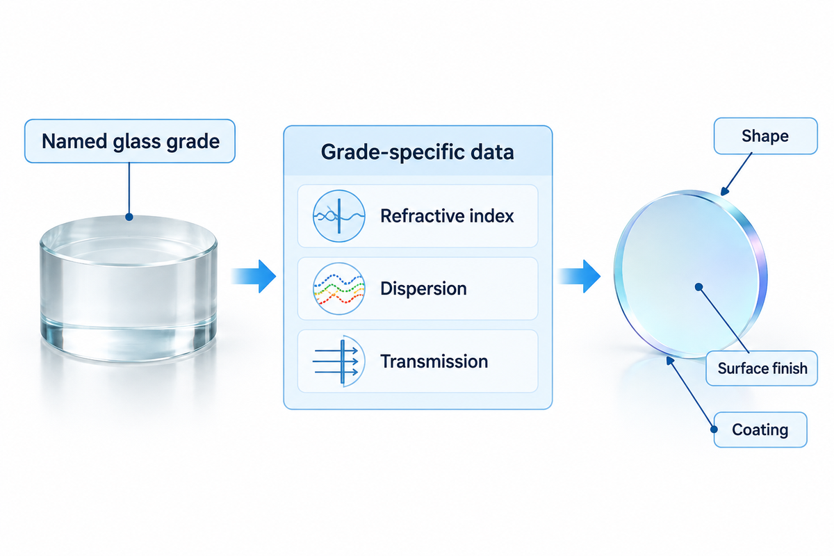
BK7 is a borosilicate crown glass from a familiar family of materials for transparent optical components. The name describes a glass material, and the finished lens or window also needs a defined shape, surface finish and coating to meet the instrument requirements. The manufacturer’s grade names make the underlying optical properties identifiable to a specific datasheet.
What Is Schott N-BK7 Glass?
SCHOTT N-BK7 glass is a named optical crown grade of SCHOTT. The published refractive index and dispersion are useful design inputs. The transmission table describes absorption through defined glass thicknesses. The generic spelling BK 7 leaves the grade open; specifying SCHOTT N-BK7 fixes the choice on the drawing.
Similar nominal optical constants are seen in crown glasses from other manufacturers. Similar index and Abbe numbers can also help an engineer determine a possible candidate for substitution. Spectral transmission, index tolerances and internal quality should also be included in the comparison. Thus, a material substitution by a supplier would affect more than the name on a quotation.
For a broader look at optical glass types, the distinction is between glass families and individual grades. Borosilicate describes a composition family; optical qualification includes the degree of control necessary for light to pass through a component with the desired imaging or measurement performance.
Which BK7 Properties Matter in an Optical Design?
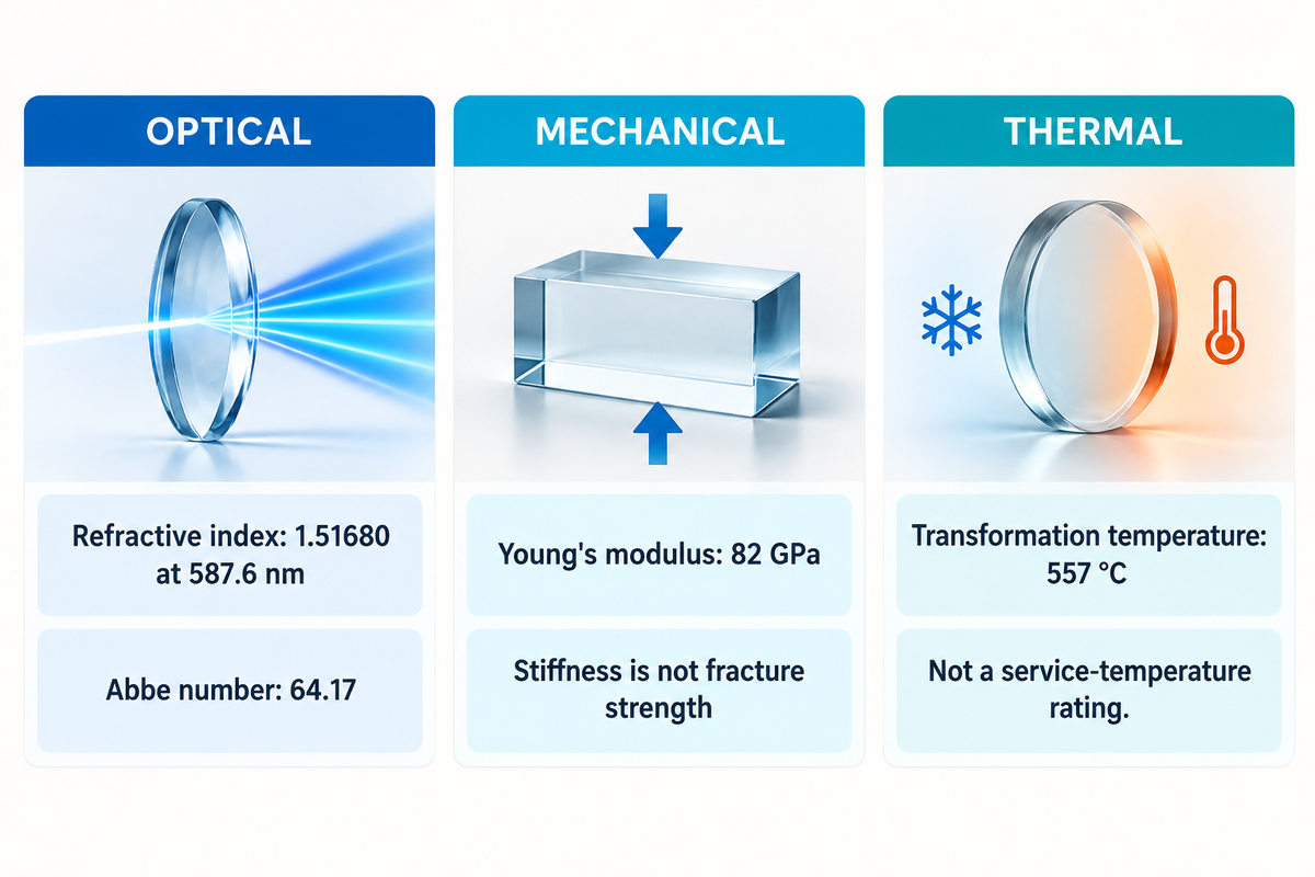
SCHOTT publishes the N-BK7 refractive index of 1.51680 at 587.6 nm with an Abbe number of 64.17. Wavelength is important because refraction varies across the spectrum. Thermal properties also have conditions: the expansion coefficient given below is valid for the stated temperature range, not for all temperatures an assembly might encounter.
| Property | Published value | Design interpretation |
|---|---|---|
| Refractive index nd | 1.51680 at 587.6 nm | Reference wavelength for the quoted index |
| Abbe number vd | 64.17 | Dispersion indicator for chromatic design |
| Index at 486.1 nm | 1.52238 | Shorter visible wavelengths bend differently |
| Index at 656.3 nm | 1.51432 | Use the correct wavelength in the optical model |
| Index at 1060 nm | 1.50669 | Visible reference index is insufficient for near-infrared design |
| Density | 2.51 g/cm³ | Mass estimate from the actual component volume |
| Linear thermal expansion | 7.1 × 10⁻⁶/K, −30 to +70 °C | Material expansion over this interval |
| Linear thermal expansion | 8.3 × 10⁻⁶/K, +20 to +300 °C | Different interval, different average coefficient |
| Thermal conductivity | 1.114 W/(m·K) | One input to heat-flow analysis |
| Young’s modulus | 82 GPa | Elastic stiffness, not a fracture-strength guarantee |
| Transformation temperature Tg | 557 °C | Glass transformation property, not a service-temperature rating |
Dispersion describes how the bending of a ray changes with color, and index is the measure of how strongly a ray is bent. Therefore, a lens can focus light of different wavelengths at different positions, even with a perfectly smooth surface. In its technical note on refractive index, SCHOTT discusses these wavelength and temperature dependencies.
Mechanical properties include stiffness and deformation, and thermal properties include expansion and thermal conductivity. Expansion affects the fit between glass and its mount, and conductivity influences heat flow through an illuminated component. Thermal-shock behavior combines material response, edge condition, mounting stress and temperature gradients in the finished assembly.
Catalogue index is the starting model for precision optics. In a NASA study of N-BK7 refractive index, absolute index was measured across wavelength and temperature. They found differences between sample-supplied data and catalog data; absolute index and index relative to air also use different reference media. For precision calculations, be sure to be consistent with the reference medium used to express absolute index.
A window designer replacing an existing window may keep the same glass grade but alter focus by changing thickness. A metrology instrument may respond to small variations in the index within the blank. Material constants, homogeneity and finished component tolerances should be shown on separate areas of the drawing.
How Do Wavelength and Thickness Change BK7 Transmission?
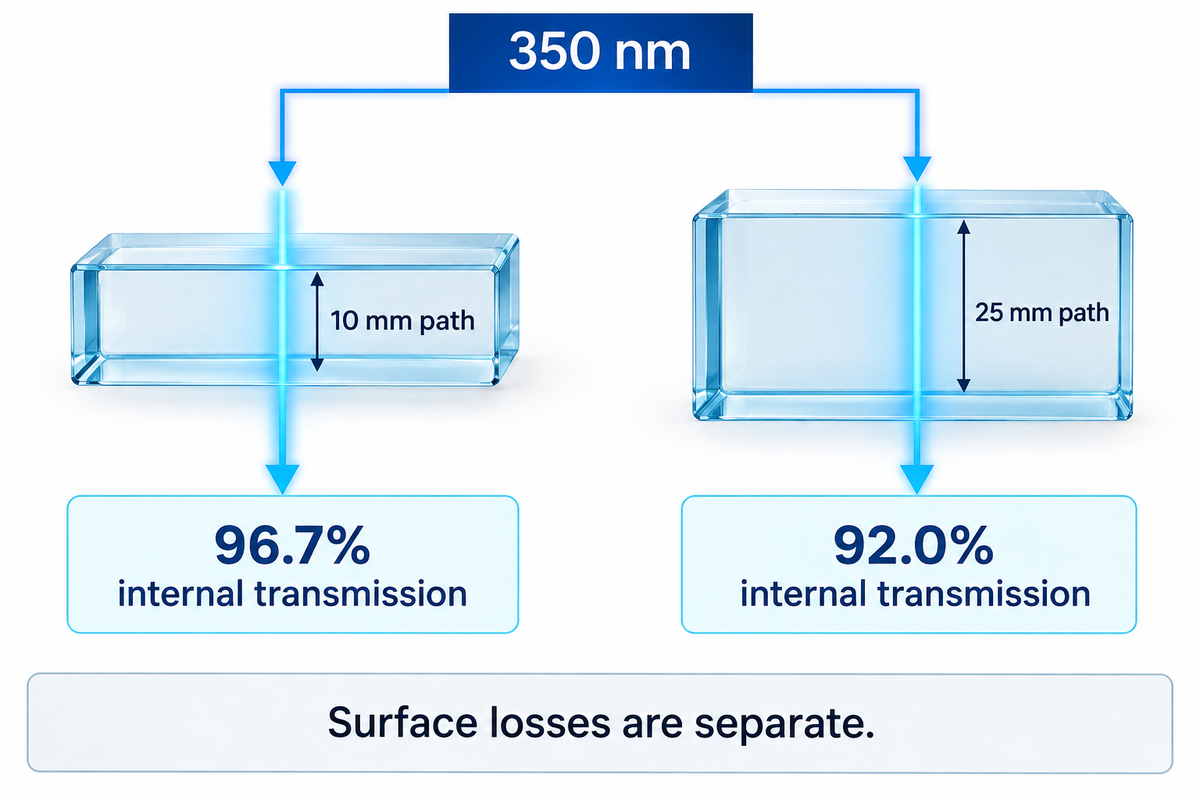
At 350 nm, SCHOTT lists N-BK7 internal transmission of 96.7% through 10 mm and 92.0% through 25 mm. A longer path absorbs more light. Internal transmittance describes the glass bulk; the measured throughput of an optical window also includes reflection and losses associated with its finished surfaces.
Wavelength–Thickness Check
The Wavelength-Thickness Check separates bulk absorption from surface losses before a material or coating is selected.
| Wavelength | 10 mm path | 25 mm path | Selection implication |
|---|---|---|---|
| 300 nm | 29.0% | 5.0% | Bulk absorption dominates this comparison |
| 320 nm | 77.0% | 52.0% | Thickness strongly changes the remaining signal |
| 350 nm | 96.7% | 92.0% | Check the actual path before accepting a UV specification |
| 365 nm | 98.8% | 97.1% | Surface losses still need a separate allowance |
| 400 nm | 99.7% | 99.2% | High bulk transmission in this visible-edge example |
| 700 nm | 99.8% | 99.6% | Component surfaces can become the larger loss |
| 1060 nm | 99.9% | 99.7% | Useful near-infrared reference point |
| 1530 nm | 99.2% | 98.0% | Include path length in the detector power budget |
| 1970 nm | 93.0% | 84.0% | Absorption increases toward this infrared region |
| 2500 nm | 67.0% | 36.0% | Compare a material suited to the required band |
A single published range like “visible and near infrared” conceals the variations in this table. The visible spectrum is comparatively forgiving for bulk transmission, but a thick prism has a longer internal path than a thin cover window. Its beam path, rather than its outside dimension alone, should be included in the calculation.
How Can You Estimate Transmission at a Different Thickness?
For homogeneous glass with linear absorption, the same wavelength and unchanged material conditions, internal transmission scales with path length. Use the 10 mm value published by SCHOTT; this value doesn’t consider reflection, scattering and coating losses. The relationship for thickness is described by the SCHOTT TIE-35, equation 1.6.
Calculated example at 350 nm:
Ti(d2) = Ti(d1)d₂/d₁
Ti(5 mm) = 0.9675/10 ≈ 0.983, or 98.3% internal transmission.
When designing an instrument, comparing a 5 mm window with the reference thickness can help estimate the improvement in bulk transmission before any coating is selected. It isn’t a prediction of the window’s delivered throughput. If the instrument requires a minimum signal at its sensor, optical budgets need to include both surfaces and the remaining optical train. Specifying a minimum transmission for procurement requires stating which of these is being accepted.
- Set the wavelength. Use the instrument band, including its edge wavelengths.
- Determine the glass path. Use the optical path inside the component at its working angle.
- Estimate internal loss. Read the correct grade table and apply the thickness relationship only within its assumptions.
- Add surface performance. Evaluate coating transmission and reflection at the intended angle and polarization.
Anti-reflective optical coatings address surface reflections. They don’t alter absorption in the glass. SCHOTT describes default transmission values in catalogs as melt medians; stricter transmission requirements warrant agreement on a material specification.
Long ultraviolet exposure adds another variable. Natura and Ehrt’s solarization research revealed dependence of transmission changes on composition in experimental BK7-type glasses. For an irradiated optical substrate, evaluation of initial transmission and transmission after the intended exposure are separate performance questions.
Where Is BK7 Used, and What Are the Limits?
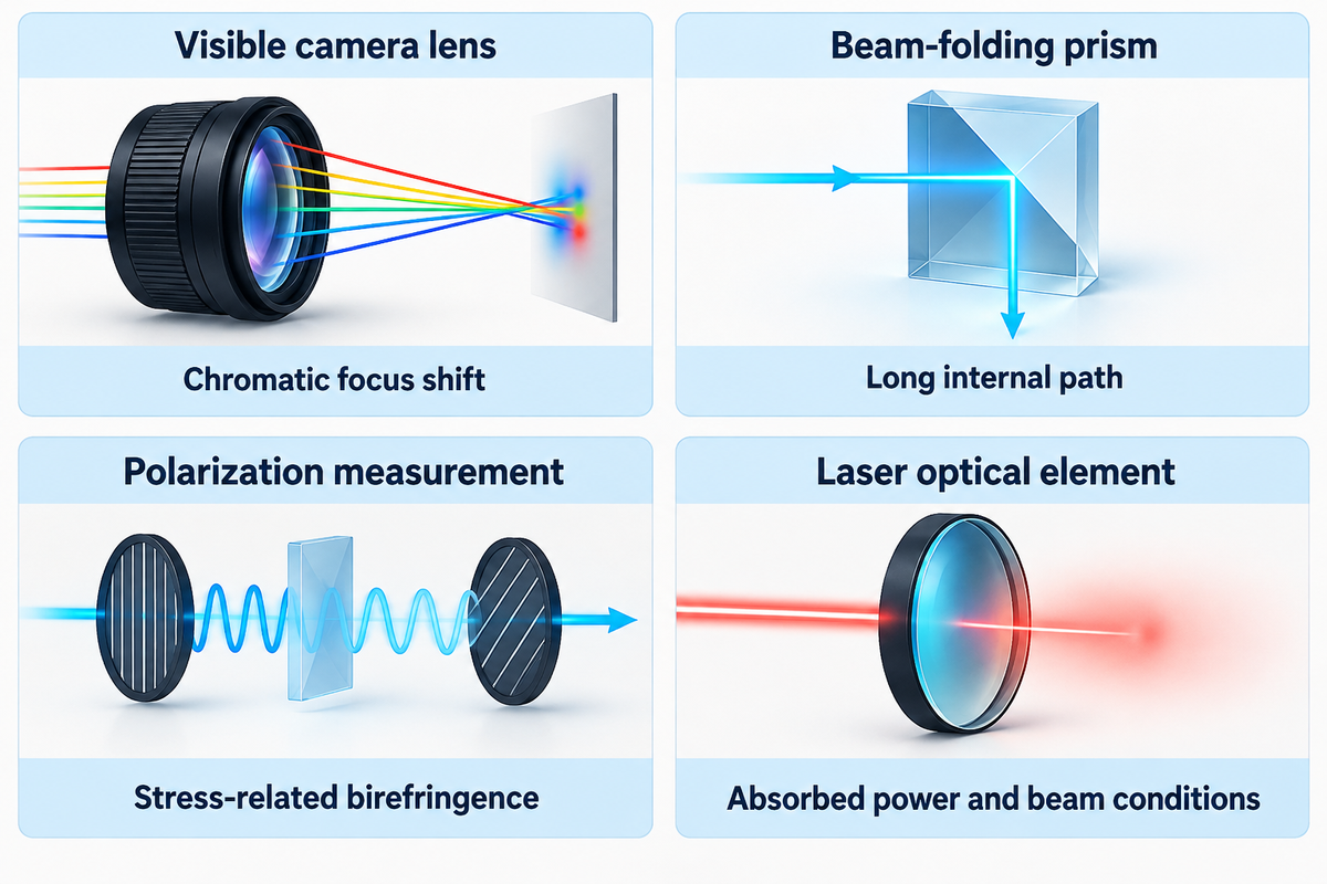
BK7 is used for imaging lenses, instrument windows, prisms and filter substrates, in cases where its transmission and optical constants are compatible with the system. Application fit depends on the finished component. Clear glasses can still produce unwanted reflection, wavefront error or polarization effects, and each use should include a performance condition to define the light path.
BK7 Application Fit Table
The BK7 Application Fit Table correlates each optical task to the property most likely to change the material or finishing choice.
| Optical task | Why BK7 is a candidate | Limiting condition | Next choice |
|---|---|---|---|
| Visible camera lens | Defined index and dispersion | Chromatic focus shift | Design the lens combination across the imaging band |
| Instrument entrance window | High visible bulk transmission | Reflection or transmitted wavefront error | Specify coating and wavefront separately |
| Beam-folding prism | Refracting and reflecting geometry | Long internal path and working angle | Calculate transmission along the ray path |
| Filter substrate | Transparent carrier for a coating | Coating band and substrate absorption | Choose the coating/substrate pair |
| Visible machine vision | Transmission in the illumination band | Glare and contamination at the front surface | Evaluate the finished window in the camera assembly |
| Near-infrared sensor window | Useful transmission at selected wavelengths | Absorption at the band’s long-wavelength edge | Check the whole specified spectrum |
| Near-UV instrument | Thin paths can retain useful transmission | Thickness and irradiation history | Compare a suitable UV-grade material |
| Polarization measurement | Transparent window substrate | Stress-related birefringence | Control mounting and polarization error |
| Laser optical element | Fabricable precision substrate | Absorbed power, coating and beam conditions | Use a component qualified for the actual laser conditions |
| Semiconductor inspection | Visible imaging path | Inspection wavelength | Separate visible inspection from deep-UV optical requirements |
Consider a camera enclosure where the window produces a reflected ghost image due to off-axis illumination. Replacing the glass alone may not address the reflection. Surface coating, the angle of the glass and the illumination geometry affect the optical path and offer different ways to address the problem. The replacement glass should be evaluated in the assembled camera, where the ghost image exists, rather than accepted solely because the sample has high clarity.
Polarization sensitivity requires a separate window check. Park, Sushkov and Budker describe window birefringence that can produce a signal indistinguishable from the sample being measured. A polarimetry window and its mounting should preserve polarization performance while transmitting sufficient light.
When Should You Choose Fused Silica Instead of BK7?
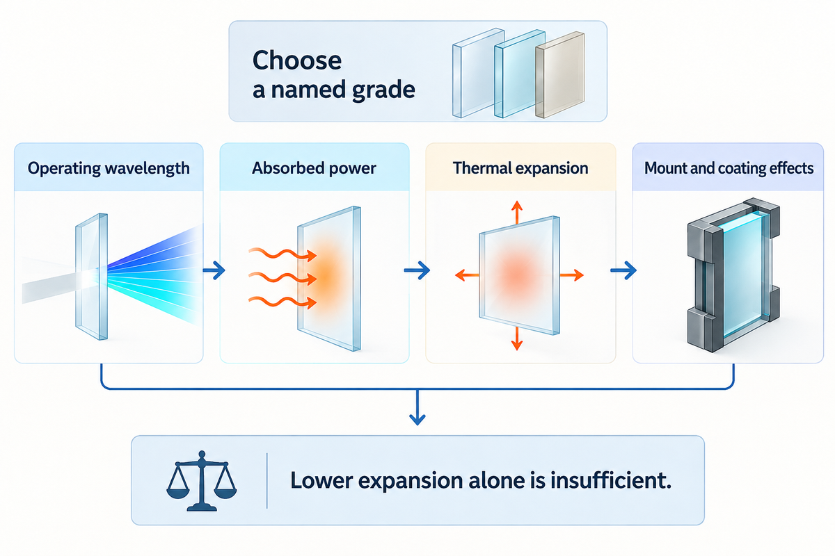
Select an appropriate fused-silica grade when the spectral absorption, or thermal expansion, of BK7 precludes the required performance. Fused silica has lower expansion, but thermal lensing also relies on the absorbed power and the temperature response of refractive index. The proper comparison is between named grades, at the instrument’s wavelength, thickness and working conditions.
High purity silica exists in grades optimized for various spectral regions. For infrared, hydroxyl content and the manufacturing route can play a role; UV performance also depends on the grade. The guide to quartz and fused silica grades provides the broader material distinctions; in the absence of specific grade information, a generic “quartz” description is too loose for a precision substitute.
Keep BK7 in consideration
- The required band fits its measured transmission.
- The assembly tolerates its thermal expansion.
- Available fabrication and coating meet the drawing.
Compare a fused-silica grade
- Bulk absorption uses too much of the signal budget.
- Expansion-driven movement limits stability.
- The specified exposure requires a different substrate.
A 2015 experiment by the University of Central Florida illustrates the effect of the glass grade. Researchers compared uncoated BK7, UV fused silica and Infrasil windows in a 2030–2050 nm beam-combining system. With a 3 mm beam and incident power up to 240 W, both BK7 and UV fused silica showed strong thermal lensing; none was measurable for Infrasil in that configuration.
The ranking describes that experiment, rather than a universal laser rating. It also explains why using UV fused silica to solve an infrared heating problem would risk an unsatisfactory result. A substitute with lower expansion might still absorb enough energy to disturb the optical path.
For a buyer considering a higher material quotation, the key question is which measured loss or movement the change addresses. If the error is due to stressed mounts or coatings, replacing the substrate may add cost while leaving the fundamental cause untouched.
What Drives BK7 Component Cost?
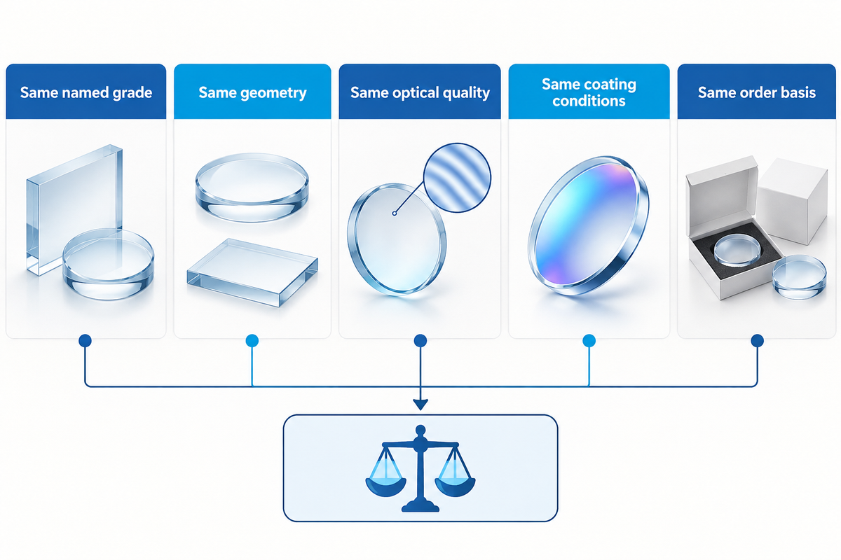
BK7 component cost depends on geometry, optical tolerances, coatings and quantity, as well as the glass blank. In the catalog prices as of October 26, 2026, Thorlabs quotes WG11010 (uncoated window) at US$97.23 and WG11010-A (coated window) at US$110.26. The pair shows a stock part difference and not a custom part quote.
Both examples use a 25.4 mm diameter, 1 mm thick N-BK7 window; the A coating covers 350–700 nm. Subtracting the listed prices gives US$13.03. The increment belongs to these catalogue variants and purchasing conditions. Quoting to coat customer-supplied glass assumes different production and handling conditions.
Consider a purchasing team examining two low cost optical windows. One quotation may accept a higher level of surface imperfections while the other may have better wavefront control and inspection. Comparing only thickness and diameter hides these differences. Before asking the supplier of the higher quotation to match the lower quotation, the team must understand what optical requirement can be relaxed while still ensuring image quality.
| Cost driver | Matching condition | Who resolves the difference? |
|---|---|---|
| Material | Named grade and permitted substitution | Optical engineering |
| Geometry | Shape, thickness, aperture and edge treatment | Mechanical engineering |
| Optical quality | Wavefront, wedge and surface requirements | Engineering and quality assurance |
| Coating | Band, angle, polarization and test conditions | Optical engineering |
| Order basis | Quantity, inspection documents and delivery scope | Procurement and finance |
Bill Thames of PFG Precision Optics covers how material selection, annealing, and fabrication influence optical production. Shops are required to grind and polish to the drawing. Polishing time depends on the required finish and the shop process and whether the glass is softer; a high-quality finish can outweigh a blank-material advantage.
How Do You Specify and Source a BK7 Component?
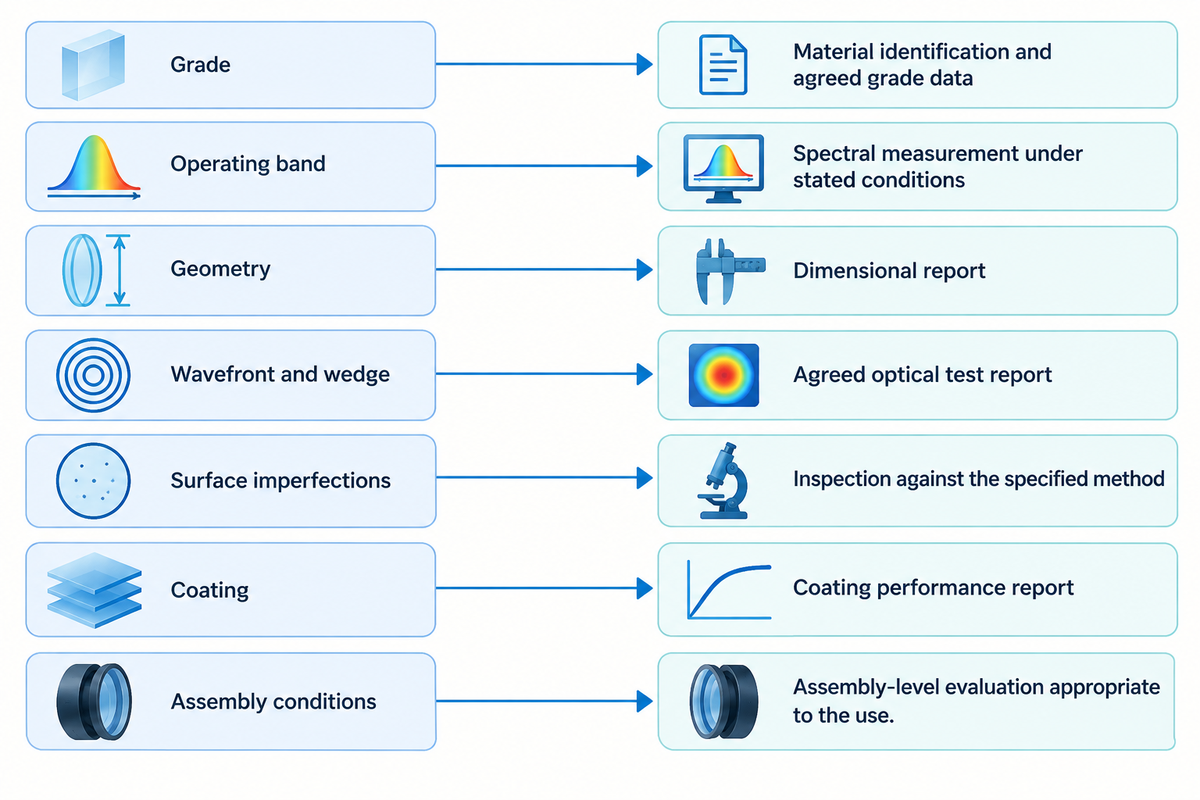
Cite the named glass grade, operating wavelength, geometry, surface quality and coating. The raw-glass quality and finished-component quality belong to different parts of the specification. Thus, procurement can compare equivalent quotations, and quality assurance can have measurable acceptance conditions rather than an undefined request for “high quality BK7.”
ISO 12123:2018 addresses raw optical glass. A material certificate and a finished-window inspection report answer different queries. For the finished optic, ISO 10110-7:2017 covers how surface-imperfection acceptance is indicated on optical drawings.
“These include localized surface imperfections, edge chips and long scratches.”
Begin with instrument requirements and carry over the constraints to the drawing. A low bubble and inclusion requirement addresses internal imperfections; it doesn’t replace surface or wavefront limits. Similarly, homogeneity controls spatial index variation, a different aspect of optical performance from the coating specification.
| Drawing field | What to enter | Acceptance evidence |
|---|---|---|
| Grade | SCHOTT N-BK7, or an explicitly approved named alternative | Material identification and agreed grade data |
| Operating band | Actual wavelengths and required transmission basis | Spectral measurement under stated conditions |
| Geometry | Diameter or outline, thickness, clear aperture and tolerances | Dimensional report |
| Wavefront and wedge | Limits with test wavelength and aperture | Agreed optical test report |
| Surface imperfections | Drawing notation and acceptance level | Inspection against the specified method |
| Coating | Band, angle, polarization and surface assignment | Coating performance report |
| Assembly conditions | Mount, adhesive or polymer contact, temperature and exposure | Assembly-level evaluation appropriate to the use |
The requirements for material purity, cosmetic appearance and optical acceptance are separate. Specify the maximum image error and state the criteria for measurement in high-quality optics. Keep the requests in the quote package for answers alongside material identification and the scope of inspection.
Named materials are supplied by glass producers; component processors fabricate parts and perform finishing; catalogue suppliers offer defined stock components. SW GLASS presents glass quality inspection and custom optical glass solutions for the component stage. Send optical requirements and drawing together to define inspection and fabrication scope.
Discuss your optical glass component
Frequently Asked Questions
Is BK7 glass suitable for UV optics?
BK7 can suit some near-UV applications when its thickness and transmission meet the instrument requirement.
Absorption rises toward shorter wavelengths, so the operating band and internal path length matter. Use the grade-specific spectral table, then include the coating and surface losses. For prolonged irradiation, also evaluate transmission after the relevant exposure; initial clarity alone leaves that question unanswered. A thin near-UV window and a thick prism can therefore lead to different material choices at the same wavelength.
What industries use BK7 glass most?
BK7 appears in imaging, instrumentation, machine vision and other optical systems.
Typical optical applications include lenses, prisms, filters and protective instrument windows. It’s a widely used optical glass, but suitability follows the optical task rather than an industry label. A semiconductor inspection camera using visible illumination and a deep-ultraviolet process tool can require very different substrates, even within the same factory.
Are BK7 and N-BK7 the same glass?
BK7 is often used as a generic description, while N-BK7 identifies a specific SCHOTT grade.
For repeatable procurement, name the manufacturer and grade on the drawing. A product described simply as BK7 glass may come with different material documentation or quality limits. Compare the supplied grade’s optical data and agreed tolerances before approving it as a replacement in an existing design. Matching one nominal index value leaves the other optical and quality requirements open.
Where can I download the N-BK7 datasheet?
SCHOTT publishes the N-BK7 datasheet through its optical-glass product documentation.
The reference used here’s SCHOTT’s December 2023 sheet. For a new design, obtain the current manufacturer version and retain its date with the optical model.
Does an AR coating improve BK7’s internal transmission?
An anti-reflective coating reduces surface reflection; it does not change the bulk glass’s internal transmission.
That distinction explains why a coating can improve finished-window throughput while the material’s absorption remains the same. Select the coating for the required band, incidence angle and polarization. If absorption through the glass already consumes too much of the available signal, the useful changes are to the material, wavelength or path length. A surface coating addresses a different loss mechanism.
References & Sources
- SCHOTT TIE-29: Refractive Index and Dispersion manufacturer technical note hosted by the University of Arizona.
- Cryogenic Temperature-dependent Refractive Index Measurements of N-BK7, BaLKN3, and SF15 NASA Goddard Space Flight Center, 2007.
- Formation of radiation defects in silicate and borosilicate glasses Ute Natura and Doris Ehrt, 1999; TIB repository.
- Precision polarimetry with real-time mitigation of optical-window birefringence Park, Sushkov and Budker, Review of Scientific Instruments.
- High-power spectral beam combining of linearly polarized Tm:fiber lasers Shah and colleagues, Applied Optics, 2015.
- Optical Glass Selection Is Not Always So Transparent a Choice Bill Thames, Photonics Spectra.
- ISO 12123:2018, raw optical glass International Organization for Standardization.
- ISO 10110-7:2017, surface imperfections International Organization for Standardization.
Compiled by SW GLASS using published technical sources. Calculated examples are identified in the text; they aren’t factory test results.
Related Posts
Trending now