Get in Touch with Saiweiglass


Refractive Index of Glass: Substrate Values, Dispersion Formulas, and AR Coating Matching for Optical Cover Glass

For standard soda-lime and optical crown sheet glasses, the refractive index of glass sits around 1.52 at 587.6 nm. Of the glass substrates compared in this article, the reference index at 587.6 nm ranges from 1.4585 for fused silica to 1.7847 for SF11 dense flint. As reported by Laser Focus World, an uncoated crown glass surface near n = 1.52 reflects about 4.26% of normal incident light. That’s a single-surface reflectance factor of R1 = 0.0426 per face. For two uncoated surfaces, direct-beam transmittance falls to a factor of (1 – R1)^2 = 0.9166 before bulk absorption. Choosing the right glass substrate, anti-reflective coating stack, and optical bonding adhesive stops that reflection loss at the source.
When our engineering team designs machine-vision enclosures or industrial touchscreens where the refractive index is defined as the ratio of wave speeds, textbook index averages won’t suffice. You need exact substrate values at specified wavelengths, chromatic dispersion numbers, and coating-to-adhesive index budgets. Below, our optical fabrication team breaks down the substrates compared in our reference table, where index values are equal to the velocity of light c of a given beam relative to glass. We also address surface index shifts due to chemical strengthening and practical tolerance rules for custom orders calibrated to a given wavelength in empty space divided by medium speed.
What Is the Refractive Index of Glass? Snell’s Law, Speed of Light, and Fresnel Reflection
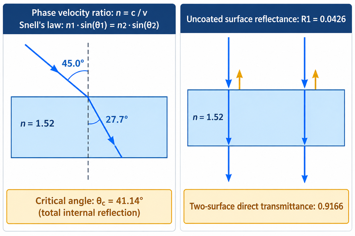
The refractive index of glass is 1.5168 for the borosilicate crown (N-BK7) and 1.5230 for B270 crown sheet at 587.6 nm. It’s the measure of how much light slows down when it passes through a transparent solid in comparison to how fast light travels in empty space. With an index of 1.52, each uncoated air-glass surface causes a normal Fresnel reflectance factor of R1 = 0.0426.
In classical optics, the refractive index of a material (denoted as n) is described as the ratio of the speed of light in free space (approximately 2.9979 × 10^8 m/s)—the speed of light in a vacuum—to the phase velocity inside the medium. In other words, the refractive index is the ratio of the speed of light in vacuum to the phase velocity of light in the material. In equation form, n = c / v, where c of a given wavelength is the speed of light in free space, approximately 2.9979 × 10^8 m/s.
Why does light slow down when going into a transparent solid? When electromagnetic radiation enters glass, the electric field of the wave perturbs the electron clouds of the silicon and oxygen ions. According to dielectric metasurface and optical material research indexed by NIH PubMed Central, dielectric optical layers alter optical path difference via effective refractive index n, and require a low extinction coefficient k. This response governs electric susceptibility and relative permittivity in the solid. For a fixed composition and approximately unchanged atomic or ionic polarizability, as the number density of the material increases, the bulk optical polarization response rises. Higher bulk polarization reduces the phase velocity and shifts index of refraction upward.
When light passes across a boundary between two media with different indices, the speed of light changes at the interface. If the ray of light strikes the surface at an oblique angle, this velocity shift causes the wavefront to refract. This light bending phenomenon is known as the refraction of light. We quantify the exact refraction angle using Snell’s law:
n1 · sin(θ1) = n2 · sin(θ2)
In Snell’s law, n1 represents the incident medium (for dry air at standard temperature and pressure, n1 ≈ 1.0003). n2 represents the refractive index of the glass medium. θ1 is the angle of incidence, and θ2 is the angle of refraction measured from the normal. This equation gives the angles and the ratio of phase velocities at the boundary of the two media. The ratio of sines of the angle of incidence and angle of refraction equals the ratio of speed between the two media. That ratio equals the phase velocity in the incident medium divided by the phase velocity in the refracting medium. You can test the refractive index of a rectangular glass block in an optics lab. Consider a light ray entering the glass slab from air. For light entering a rectangular glass slab making an angle at 45.0° to the normal, a glass index of 1.52 gives an internal refraction angle of θ2 = 27.7°.
“An uncoated surface of crown glass, such as SCHOTT N-BK7 with an index of refraction around 1.52 at 550 nm, reflects about 4.26% of incident light at normal incidence.” Laser Focus World, Thin-Film AR Coating Design Principles
Refraction also governs total internal reflection when light travels from a higher refractive index medium toward a lower one. Let’s consider light in n = 1.52 glass that strikes an air boundary above the critical angle θc = 41.14°. In such a case, 100% of the beam reflects internally without escaping into the air. At 0° normal angle of incidence, however, an impedance mismatch between air and glass causes surface reflection governed by the speed in space divided by its velocity v inside the glass. The normal-incidence Fresnel reflection equation provides the single-surface reflectance factor R1:
R1 = ((n2 – n1) / (n2 + n1))^2
For a standard glass sheet with a refractive index of 1.5, single-surface reflection is ((1.5 – 1.0) / (1.5 + 1.0))^2 = 0.0400. At n = 1.520, the single-surface reflectance factor rises to R 1 = 0.0426. For a non-absorbing plate at normal incidence, direct-beam transmittance through two identical uncoated surfaces is (1 – R1)^2 = 0.9166. For all incoherent multiple internal reflections, the total transmittance is (1 – R1) / (1 + R1) = 0.9183. Because the refractive index determines both ray bending and boundary reflection, every optical cover lens specification starts with substrate selection.
Refractive Index of Glass by Substrate: 9-Material Master Reference Table
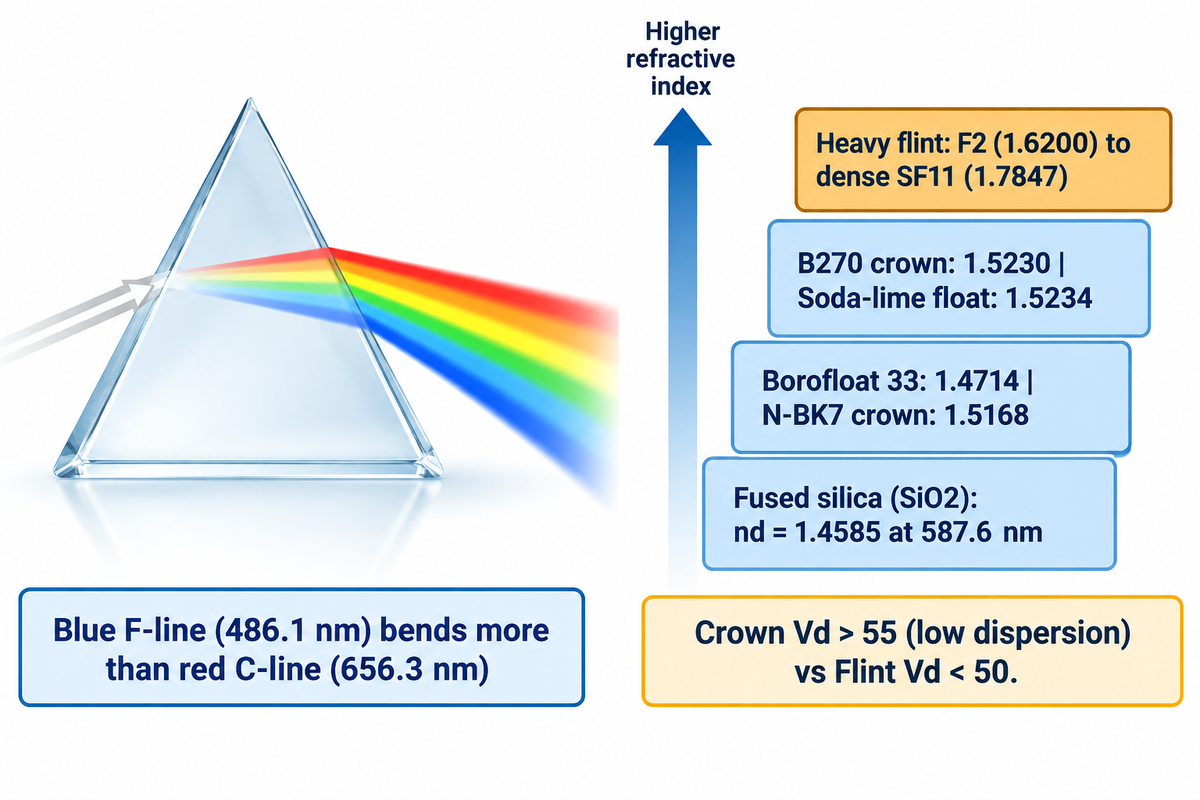
Across the optical substrates compared below at 587.6 nm, the refractive index increases from 1.4585 in fused silica to 1.4714 in Borofloat 33 borosilicate float. In the crown glass family, N-BK7 reaches 1.5168 and B270 crown hits 1.5230. Heavy flint glasses climb much higher, reaching 1.6200 in F2 and 1.7847 in dense SF11.
Engineers cannot always treat glass as a single optical constant. At 587.6 nm, the listed Borofloat 33 borosilicate glass has a refractive index of 1.4714, compared with 1.5234 for the listed clear soda-lime float glass. Conversely, introducing heavy metal oxides, such as barium, lanthanum, or lead oxides, pushes the glass toward a high refractive index. Lead-containing flint glasses combine high refractive index with strong visible dispersion, while lanthanum and barium crown glasses can combine high refractive index with lower dispersion. In NIST precision refractometry on fused silica, pure amorphous silicon dioxide (SiO2) measures 1.4585 at 587.6 nm. Among the glass substrates listed here, fused silica has the lowest refractive index at 587.6 nm. Meanwhile, borosilicate crown N-BK7 and B270 are widely used in lenses and windows for industrial cameras.
The table below compares eight glass substrates and includes sapphire as a crystalline ninth reference material. Values are referenced to the yellow helium d-line (λd = 587.6 nm, close to the sodium D-line at 589 nm) at 20 °C. The table draws on benchmark datasets from NIST, RefractiveIndex.INFO, and Präzisions Glas & Optik (PGO).
| Substrate Material & Grade | Refractive Index nd (587.6 nm) | Blue / Red Index (nF 486.1 nm / nC 656.3 nm) | Abbe Number (Vd) | Density (g/cm^3) | Visible Dispersion (nF – nC) | Single-Surface Reflectance Factor (R1) | Primary Industrial Application |
|---|---|---|---|---|---|---|---|
| UV Fused Silica / Fused Quartz (SiO2) | 1.4585 | 1.4631 / 1.4564 | 67.82 | 2.20 | 0.0067 | 0.0348 | UV-C optics, laser windows, high-temp sight glass |
| Borosilicate Float (SCHOTT Borofloat 33) | 1.4714 | 1.4764 / 1.4692 | 65.41 | 2.23 | 0.0072 | 0.0364 | Thermal viewport windows, biomedical microfluidic slides |
| Borosilicate Crown (SCHOTT N-BK7) | 1.5168 | 1.5224 / 1.5143 | 64.17 | 2.51 | 0.0081 | 0.0422 | Precision imaging lenses, prisms, calibration windows |
| Low-Iron Ultra-Clear Float Glass | 1.5180 | 1.5242 / 1.5154 | 58.90 | 2.50 | 0.0088 | 0.0423 | Solar panels, outdoor digital signage cover glass |
| Crown Sheet Optical Glass (SCHOTT B270) | 1.5230 | 1.5293 / 1.5203 | 58.50 | 2.55 | 0.0090 | 0.0430 | Machine-vision sensor covers, high-clarity scanner beds |
| Standard Soda-Lime Clear Float Glass | 1.5234 | 1.5293 / 1.5211 | 63.97 | 2.52 | 0.0082 | 0.0430 | Standard instrumentation panels, indoor display glass |
| Medium Flint Optical Glass (SCHOTT F2) | 1.6200 | 1.6321 / 1.6150 | 36.37 | 3.61 | 0.0171 | 0.0560 | Achromatic doublet lenses, dispersion-correcting elements |
| Dense Flint Glass (SCHOTT SF11) | 1.7847 | 1.8065 / 1.7760 | 25.76 | 4.74 | 0.0305 | 0.0794 | High-power refractive lenses, compact optical assemblies |
| Synthetic Sapphire (Al2O3 O-ray Crystal Reference) | 1.7682 | 1.7756 / 1.7649 | 72.20 | 3.98 | 0.0107 | 0.0769 | Extreme-abrasion defense windows, barcode scanner plates |
Observe how the refractive index varies with wavelength in the various rows of the table. In the visible normal-dispersion region of common optical glasses, shorter wavelengths have a higher refractive index than longer wavelengths. As a result, in the visible region of normal dispersion, blue light (λF = 486.1 nm) bends more than red light (λC = 656.3 nm) at the edge of the prism. This variation is known as chromatic dispersion. In high-end optical assemblies, uncorrected dispersion causes chromatic aberration where colors focus at different planes.
Optical designers quantify dispersion using the Abbe number Vd, defined as Vd = (nd – 1) / (nF – nC). Crown glasses and optical-grade fused quartz and silica substrates exhibit high Abbe numbers (Vd > 55), meaning very low color separation. Flint glasses doped with heavy oxides exhibit low Abbe numbers (Vd < 50) and strong dispersion. Within a glass grade’s fitted wavelength range, engineers use the three-term Sellmeier dispersion equation to calculate refractive index as a function of wavelength:
n^2(λ) – 1 = (B1 · λ^2) / (λ^2 – C1) + (B2 · λ^2) / (λ^2 – C2) + (B3 · λ^2) / (λ^2 – C3)
In this equation, λ is the vacuum wavelength in micrometers. The constants Bi and Ci are experimentally determined Sellmeier coefficients for a given family of glass melts.
Comparing N-BK7, B270, Aluminosilicate, and Fused Quartz for Optical Cover Lenses
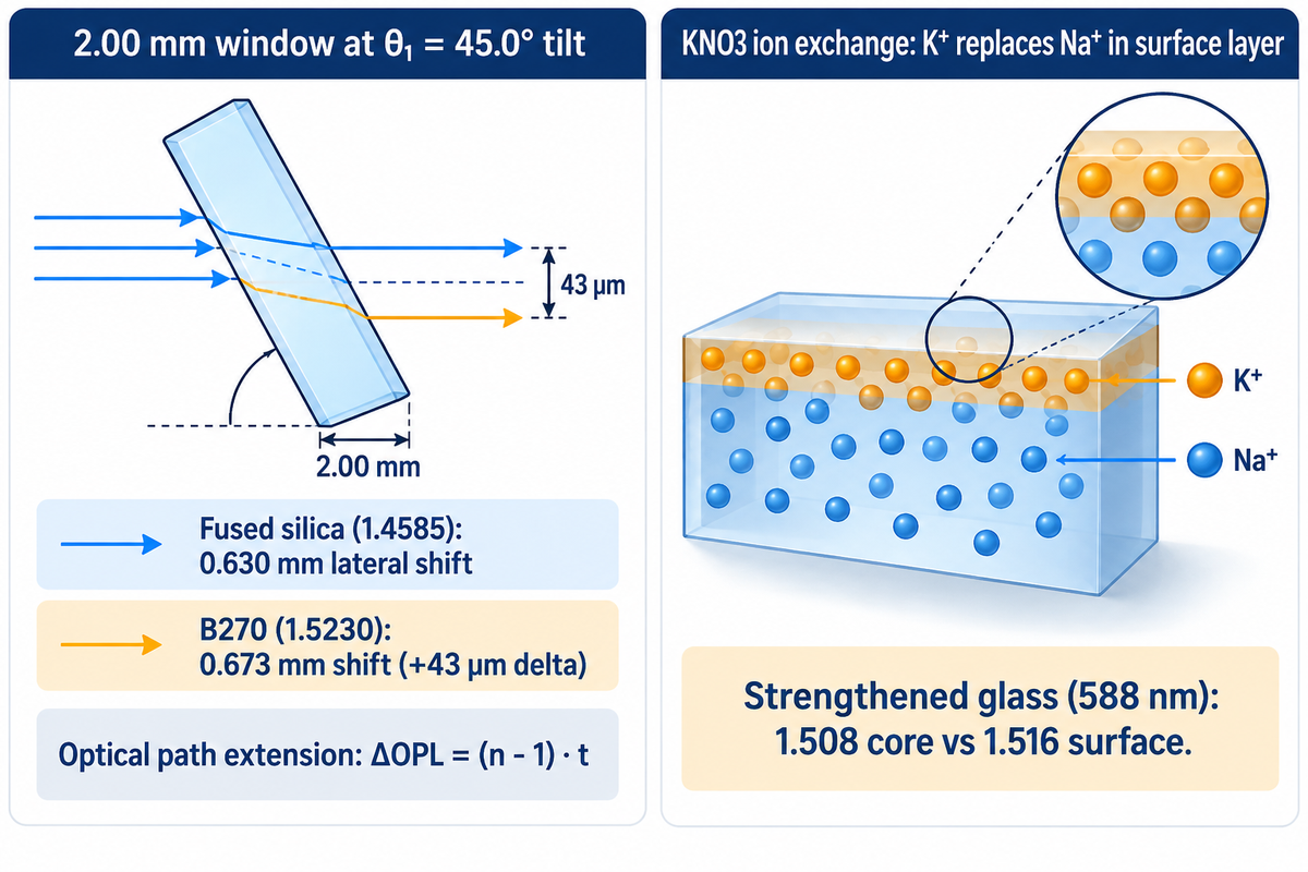
Flat protective cover lenses with N-BK7 (1.5168) and B270 (1.5230) have similar normal-incidence direct transmittance factors of 0.9158 to 0.9174. As reported by Abrisa Technologies, chemically strengthened cover glass examples have a core index of 1.508 and a potassium-exchanged compression-layer index of 1.516 at 588 nm. Meanwhile, UV fused quartz (1.4585) lowers the single-surface reflectance factor down to R1 = 0.0348 for ultraviolet and laser enclosures.
Many mechanical engineers believe that flat cover windows have zero optical power, so differences in substrate indices are negligible. While a plane-parallel window doesn’t focus collimated light, its index does control two geometric effects. The first is optical path length extension, and the second is oblique lateral beam displacement.
When a converging or diverging optical beam intersects a flat window of thickness t, optical path length increases by ΔOPL = (n – 1) · t. In paraxial imaging, this slab introduces a longitudinal focal shift of Δf ≈ t · (n – 1) / n. However, in LiDAR and machine vision housings, it’s the lateral shift d, when light crosses a tilted glass plate that’s of the utmost importance.
d = t sin(θ1) [ 1 – cos(θ1) / sqrt(n^2 – sin^2(θ1)) ]
Consider a 2.00 mm thick protective window tilted at θ1 = 45.0° in front of a coaxial laser receiver. For the stated geometry, switching from fused silica (n d = 1.4585) to B270 (n d = 1.5230) increases lateral displacement from approximately 0.630 mm to 0.673 mm, a difference of about 43 µm, or 8.6 times a 5 µm pixel pitch. The refractive index of a tilted plane-parallel window determines the lateral displacement of the beam; for a collimated beam focused by an ideal downstream lens without clipping, the displacement of the beam doesn’t affect the position of the focal spot.
What happens when you request chemically strengthened glass for custom CNC-machined optical cover glass? During potassium ion-exchange chemical strengthening, the glass sheet is submerged in a molten KNO3 salt bath. Large potassium ions (K+) diffuse into the surface and replace smaller sodium ions (Na+) to form a surface compression layer.
Abrisa Technologies reports a core refractive index of 1.508 and a potassium-exchanged compression-layer index of 1.516 at 588 nm for the glass example in its specialty glass brochure. At 633 nm and 780 nm, Abrisa lists 1.506 versus 1.514 and 1.502 versus 1.510. Abrisa Technologies reports a core refractive index of 1.50 and a compression-layer index of 1.51, for chemically strengthened Corning Gorilla Glass 3, at 590 nm. A laterally uniform surface index gradient produces no lateral beam steering at normal incidence, but it can affect optical phase and reflection; stress birefringence can also affect polarization-sensitive imaging. More positively, a surface index profile permits prism coupling stress sensors to determine surface compressive stress and depth of layer. As confirmed in clinical and geometric optics references on NCBI Bookshelf, bulk ray bending follows the core index, whereas boundary reflectance depends on the interface index.
How to Match AR Coatings, ITO Layers, and OCA Adhesives to Glass Refractive Index
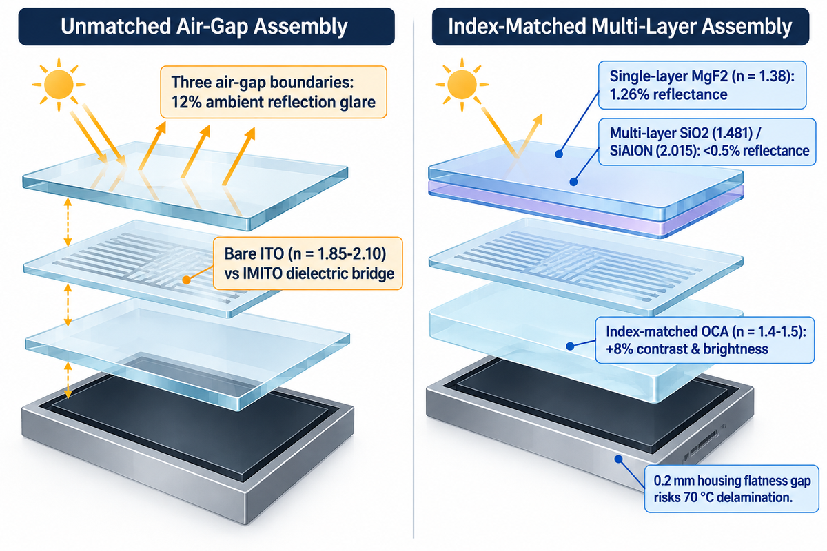
For an ideal single-layer quarter-wave coating on n = 1.52 glass in air, the coating index to achieve zero reflection at normal incidence at the design wavelength is approximately 1.233. Replacing the internal air cavity with an optically clear adhesive (n = 1.4 to 1.5 as reported by Boyd Corporation) on the back surface of the display cover suppresses the internal reflection at the glass boundary.
In an industrial touch display, light must cross multiple optical boundaries before a user sees the image. According to Boyd Corporation’s engineering analysis of optically clear adhesives, air (n = 1.0) against a touch panel or polarizer (n = 1.5) causes 4% Fresnel reflection per boundary. Across three air-gap boundaries, 12% of ambient light is reflected back as glare, degrading screen contrast by 12% and reducing display brightness by 12%. According to Boyd Corporation, replacing the air gap with index-matched OCA (n = 1.4–1.5) leaves only the 4% top-surface reflection and improves both screen contrast and brightness by 8%.
To balance each interface across the display stack, our optical engineers compare the boundary reflection factors as follows:
| Display Stack Boundary | Unmatched Media Pair (n1 → n2) | Unmatched Reflectance Factor (R) | Index-Matched Engineering Solution | Matched Media Pair (n1 → n2) | Matched Reflectance Factor (R) |
|---|---|---|---|---|---|
| 1. Front Air → Cover Glass (Single-Layer Option) | Air (1.0003) → Glass (1.520) | 0.0426 | Single-layer MgF2 (n = 1.38) QWOT AR | Air → MgF2 (1.38) → Glass | 0.0126 |
| 1b. Front Air → High-End AR Glass (Multilayer Option) | Air (1.0003) → Glass (1.520) | 0.0426 | Multi-layer sputtered SiO2 / SiAlON or Nb2O5 BBAR | Graded effective impedance stack | <0.0050 (0.0030 peak) |
| 2. Rear Cover Glass → Cavity | Glass (1.520) → Air Gap (1.0003) | 0.0426 | Index-matched OCA film or LOCA resin (n = 1.4–1.5) | Glass (1.520) → OCA (1.490) | 0.0001 |
| 3. Cover Glass → ITO Touch Layer | Glass (1.520) → Bare ITO (1.950) | 0.0154 | Index-Matched ITO (IMITO) SiO2/Nb2O5 undercoat | Matched dielectric impedance bridge | <0.0020 |
| 4. Cavity → Display Polarizer | Air Gap (1.0003) → Polarizer (1.500) | 0.0400 | Direct OCA / OCR lamination (n = 1.4–1.5) | OCA (1.490) → Polarizer (1.500) | <0.0001 |
At the front air-to-glass surface, a single-layer quarter-wave optical thickness (QWOT = λ / 4) coating uses the geometric mean nAR = √(nair · nglass). Because no durable bulk fluoride exists at 1.233, single-layer coatings use magnesium fluoride (MgF2, n = 1.38) to reach 1.26% reflectance as reported by Laser Focus World. To achieve broadband antireflection on multi-layer anti-reflective coated glass, magnetron sputtering alternates high-index and low-index oxides. Typical stacks pair high-index TiO2 (n ≈ 2.35), Nb2O5 (n ≈ 2.30), or SiAlON (n = 2.015) with low-index SiO2 (n = 1.46–1.48). As shown in US Patent US9726786B2 on scratch-resistant anti-reflective cover glass, alternating SiO2 (1.481) and SiAlON (2.015) layers achieves sub-0.5% single-side reflectance (99.27%–99.72% single-interface transmittance) and ≥12 GPa Berkovich hardness.
Inside the stack, projected-capacitive (PCAP) touch sensors and EMI-shielded windows introduce another index step: Indium Tin Oxide (ITO). Bare sputtered ITO has a high refractive index of 1.85 to 2.10 across the visible spectrum. Using the normal-incidence Fresnel model above, an ITO index of 1.85–2.10 against n = 1.52 glass gives a reflectance factor of approximately 0.0096 to 0.0257. In direct sunlight, that index jump makes etched diamond touch patterns visibly ghost across the screen. Specifying Index-Matched ITO (IMITO) provides a solution. Depending on design, IMITO can be fabricated to incorporate nanoscale dielectric bridges to minimize ghosting. The primary goal of incorporating IMITO is to reduce the ghosting effect across the etched touch screen patterns and make them virtually invisible to the human eye.
Finally, when specifying sunlight-readable optical bonding assemblies, mechanical flatness is just as important as adhesive index. Field reliability data reported by CDTech Electronics on 28- to 37-inch bar displays shows how mechanical gaps lead to delayed failures. Specifically, a 0.2 mm housing flatness gap can cause a batch with 98% initial lamination yield to delaminate at 70 °C. LOCA can fill uneven gaps around ceramic silk-screen borders, but trapped air, poor wetting, and cure shrinkage can still produce bubbles or voids.
How Refractive Index Is Measured and What Tolerances OEMs Should Specify
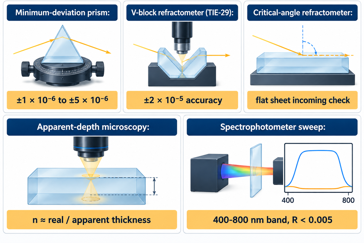
SCHOTT TIE-29 reports enhanced V-block refractometer accuracy of ±2 × 10^-5; ASTM C1648 guides the selection of refractive-index and dispersion measurement methods. For precision optical blanks, SCHOTT TIE-29 documents homogeneity grade H1 at ±2 × 10^-5, whereas flat strengthened cover glass drawings specify prism-coupler surface stress testing and spectral reflectance verification.
How do laboratories and glass factories actually find the refractive index of a production batch? Refractive-index measurement methods comprise, for example, minimum-deviation prisms, V-block refractometry, critical-angle refractometry and apparent-depth microscopy. Relevant optical material and test methods are listed in ISO ICS 37.020. Our OEM Cover Glass Optical Metrology & Verification Matrix presents a discussion of these methods.
| Measurement Method & Reference | Typical Capability / Viewing Condition | Sample Preparation Required | Primary Use Case in Optics Manufacturing | Recommended OEM Drawing Callout |
|---|---|---|---|---|
| Minimum-Deviation Prism Goniometer (Primary Lab Standard) | ±1 × 10^-6 to ±5 × 10^-6 | Polished 60° apex prism from melt | National metrology (NIST) & master catalog constants | Never specify for cover glass; reserved for space/lithography lenses |
| V-Block Refractometer (SCHOTT TIE-29 / ASTM C1648) | SCHOTT TIE-29 reports enhanced V-block refractometer accuracy of ±2 × 10^-5 | 2 perpendicular polished faces + contact fluid | Optical glass melt-lot certification (N-BK7, F2, SF11) | ASTM C1648 guides the selection of refractive-index and dispersion measurement methods |
| Critical-Angle Refractometer (Factory Incoming Inspection) | Rapid critical-angle prism interface reading | Flat polished sheet + contact liquid | Incoming verification of flat float & crown sheets | Standard substrate family verification for B270 and float glass |
| Apparent-depth microscopy | Near-normal, paraxial viewing in air | Transparent flat window | Approximate substrate-index estimation | n ≈ real thickness / apparent thickness |
| Spectrophotometer Spectral Transmittance & Reflectance Sweep | Direct spectral curve verification across target band | Finished AR/AF coated cover lens | Production batch certification of coated display & sensor windows | Primary QC gate: specify target wavelength band (400–800 nm) and R < 0.005 |
One frequent blunder made by designers of optical systems is shown in the following example. An engineer copies a lens-blank specification with a ±0.0005 nominal-index tolerance and H2 homogeneity, corresponding to a maximum refractive-index variation of 5 × 10^-6, onto a flat cover-glass drawing. Requesting lens-grade melt certification on flat float or crown cover sheets adds unnecessary prism-lot testing without improving flat window transmission.
“Thin-film optical coating monitors are far less able to cope with refractive-index errors in the deposited film layers than with simple physical thickness errors.” ‐ Macleod, Applied Optics (Optica Publishing Group)
Macleod demonstrated this principle in peer-reviewed thin-film sensitivity research published in Optica’s Applied Optics. Thin film refractive index and physical film thickness both affect AR coating performance. Optical monitors must carefully control the refractive index of the sputtered layers (SiO2 and Nb2O5). For a flat protective cover window, specify the nominal substrate grade (such as B270 at nd = 1.5230 or N-BK7 at nd = 1.5168 with polished thickness tolerances down to ±0.025 mm on 0.50-3.00 mm substrates per PGO) and enforce spectrophotometer transmittance limits across your sensor band. Spectrophotometric transmittance limits over the sensor passband should be enforced.
Specifying Custom AR-Coated and Chemically Strengthened Cover Glass for Production
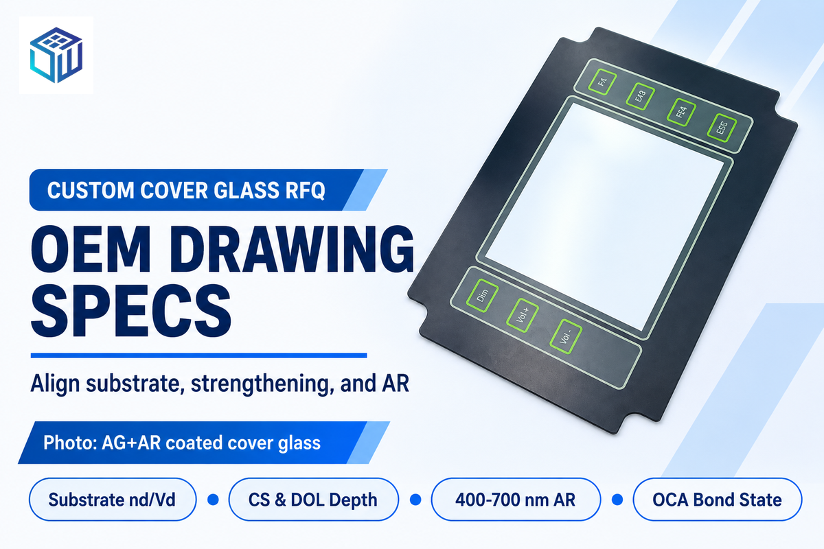
When specifying custom optical cover glass to optimize transmission, OEM engineering drawings need to address six key parameters. These include substrate grade, physical sheet thickness (0.33 to 15.0 mm) with CNC outer profile tolerance (±0.05 mm), and chemical strengthening depth. The drawings also need to define the target spectral band, the sequence of surface coatings, and the index of the adhesive used for rear bonding.
There’s rapidly increasing demand for integrated optical cover assemblies worldwide. Market data from Grand View Research shows the global optical coatings sector reached USD 24.1 billion in 2025, growing at an 8.4% CAGR through 2033. Meanwhile, Mordor Intelligence reports that electronic devices capture 36.60% of global anti-reflective coating volume. Splitting raw glass cutting, chemical strengthening, and vacuum AR coating across separate vendors often causes index-mismatch blame games when final transmittance drops.
At Dongguan Saiwei Glass Co., Ltd. (SW Glass), we integrate CNC glass machining, ion-exchange strengthening, and cleanroom magnetron-sputtered AR and AF optical coating under one factory roof. Before forwarding your next cover lens drawing for quotation, we recommend verifying these six specification items:
- 1. Substrate Family and Nominal Index (nd/Vd): Call out the exact base material rather than generic optical glass. Examples of commonly used glasses include UV fused silica (1.4585), Borofloat 33 (1.4714), chemically strengthened Aluminosilicate (1.508 core at 588 nm per Abrisa), N-BK7 (1.5168), and B270 (1.5230).
- 2. Thickness and CNC Dimensional Profile: Specify sheet thickness from 0.33 mm sensor covers up to 15.0 mm industrial sight windows. Include ±0.05 mm CNC edge profile tolerance, 2.5D chamfer geometry, and ISO 10110-5 optical surface flatness standards where laser wavefronts pass through.
- 3. Chemical Strengthening Profile (CS and DOL): Indicate the level of surface compressive stress and DOL, and specify verification of potassium ion exchange surface index via prism-coupler stress refractometry.
- 4. Target Spectral Band and Angle of Incidence: Define whether the AR coating targets visible light (400–700 nm) or near-infrared LiDAR bands (850, 905, or 940 nm). Always note the nominal angle of incidence (0° versus 30°–45°).
- 5. Surface Treatment Stack Order: Clarify which faces receive Anti-Glare (AG acid-etched surface haze), Anti-Reflective (AR), and Anti-Fingerprint (AF, water contact angle ≥110°). Also indicate the ceramic or dead-front printing on the reverse surface of the part.
- 6. Optical Bonding Interface State: Inform our coating engineers if the rear surface is in contact with either air or an optical bonding adhesive. Double-sided AR coating reduces reflections from both faces of an air-spaced cover; OCA/LOCA bonding (n ≈ 1.48-1.51) reduces rear-interface reflection through index-matching and can be done with bare glass or a coating designed for the bonded interface.
Frequently Asked Questions About the Refractive Index of Glass
Q1: Why is the refractive index of glass greater than water?
At 587.6 nm, standard soda-lime glass has a refractive index of 1.52 compared with 1.333 for liquid water. When light enters a dense silicate glass network, electronic polarization of the constituent ions reduces the optical phase velocity to roughly 1.97 × 10^8 m/s. In liquid water, light propagates faster at about 2.25 × 10^8 m/s.
Q2: What is the refractive index of glass with respect to water?
The relative refractive index of standard crown or soda-lime glass (1.52) with respect to water (1.333) is 1.140. Since this value is near 1.0, submerging uncoated glass in water reduces the boundary impedance mismatch. The single-surface normal Fresnel reflectance is reduced from a factor of R1 = 0.0426 (for an air boundary) down to R1 = 0.0043 (for a water boundary).
Q3: Does glass thickness or tempering change its refractive index?
Glass thickness does not change the intrinsic refractive index, which is an intensive property fixed by chemical composition and wavelength. However, thicker glass does increase the total optical path length and lateral beam shift at oblique incidence angles. Stress birefringence is introduced during thermal tempering. Abrisa Technologies reports a core refractive index of 1.50 and a compression-layer index of 1.51 for chemically strengthened Corning Gorilla Glass 3 at 590 nm.
Q4: Which color of light has the highest refractive index in glass?
Violet and blue light experience the highest refractive index in the visible normal-dispersion region of optical glass. Shorter wavelengths interact much more strongly with the electronic resonance frequencies of the ultraviolet absorption edge. In SCHOTT N-BK7, violet g-line light (435.8 nm) has a refractive index of 1.52668, while blue F-line light (486.1 nm) measures 1.52238. Red C-line light (656.3 nm) drops to 1.51432.
Q5: Can optical glass have a refractive index below 1.45 or above 1.90?
Crystals of CaF2 exhibit a refractive index of approximately 1.433–1.434 at λ=587.6 nm; SCHOTT N-FK51A is a fluor-crown glass with a higher refractive index. Extremely dense lanthanum, tellurium and bismuth heavy-flint glasses reach refractive indices from 1.922 up to 2.10. Designers of these ultra-high index glasses use them in the fabrication of compact, high numerical aperture lenses and lithography systems for the semiconductor industry.
References & Sources
- The National Institute of Standards and Technology (NIST) – Absolute Refractive Indices and Thermal Coefficients of Fused Silica and Calcium Fluoride (Principal wavelength dispersion and temperature coefficient metrology).
- NIH PubMed Central (PMC9231017) – High-Refractive-Index Dielectric Materials and Optical Phase Control (Relationships of refractive index n and the extinction coefficient k).
- International Organization for Standardization (ISO ICS 37.020) Optical Equipment, Optical Materials, and ISO 10110 / ISO 9802 Standards Catalog (International standards catalog for optical materials and drawing specifications).
- Optica Publishing Group (Macleod, Applied Optics, Vol. 20, Issue 1) – Monitoring of Optical Coatings and Refractive Index Error Sensitivity (Error sensitivity of multilayer AR coatings with respect to refractive index n and thickness).
- Google Patents (US9726786B2) – Cover Glass Articles with Scratch-Resistant Anti-Reflective Coatings (Multi-layer SiO2 AR coatings (n=1.481) and SiAlON (n=2.015) layers with Berkovich hardness ≥12 GPa).
- National Center for Biotechnology Information (NCBI Bookshelf NBK592413) – Optics and Refraction Reference (Clinical and physical refraction fundamentals across optical media).
- Laser Focus World Thin-Film Coatings: Understanding Key Design Principles of Antireflection Coatings (Fresnel reflection math at 4.26% per surface for n=1.52 crown glass and quarter-wave AR design). Anti-reflection coatings are designed to have a quarter-wave of thickness in relation to the refractive index of the substrate for optimal function.
- RefractiveIndex.INFO Optical Constants Database SCHOTT N-BK7 and Soda-Lime Clear Glass Optical Constants (Sellmeier dispersion coefficients, Abbe numbers, and normal reflectance data).
- Präzisions Glas & Optik (PGO) SCHOTT N-BK7 Borosilicate Crown Technical Datasheet (Multi-wavelength refractive indices nd, nF, nC and physical properties).
- Boyd Corporation Technical Guide: Discussion of Optically Clear Adhesives (OCA) and Display Reflection Loss (Three-boundary 12% air-gap reflection loss and 8% optical bonding contrast and brightness improvement).
Related Posts
Trending now