Get in Touch with Saiweiglass



Updated November 2026
The standard magnification of ocular lens assemblies on modern optical stands is 10x. That 10× rating corresponds to a 25 mm focal length at the 250 mm viewing reference (OpenStax College Physics 2e). Active commercial eyepiece lines span 10× to 20×. Specialized inspection barrels extend from 5× (50 mm focal length) to 30× (8.3 mm) with 6 mm to 26.5 mm Field Numbers.
Changing eyepiece power alters visual angle, visible specimen area, and exit-pupil height above the eye element. However, ocular power doesn’t affect details limited by diffraction. True optical limits are governed by objective numerical aperture and illumination wavelength.
Quick Answer: A standard ocular lens enlarges the intermediate image by 10× (f = 25 mm). Multiply objective power by ocular power for visual magnification. Divide Field Number by objective power for specimen diameter, and cap total power at 500–1,000 × NA.
What Is the Typical Magnification of an Ocular Lens, and Why Is 10x the Industry Default?
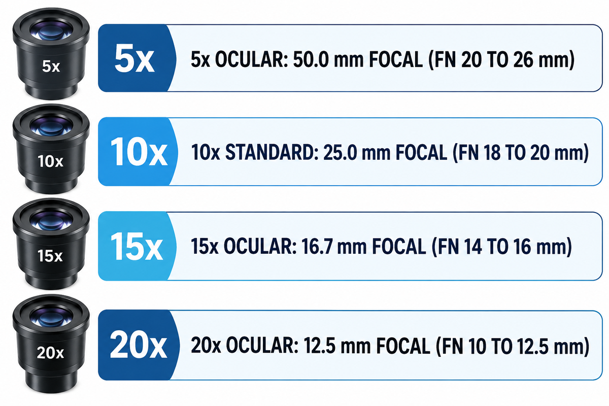
Standard laboratory eyepieces provide a magnification of 10x from a 25 mm focal length, while specialized tubes span 5× to 30×. Manufacturers fit almost every compound microscope and stereo stand with a 10x eyepiece by default. That 25 mm focal ratio preserves a comfortable 1.0 mm to 2.5 mm exit pupil alongside wide 18 mm to 26.5 mm diaphragms.
In a light microscope, the primary function of the ocular lens is collimating the intermediate focus for relaxed viewing. Students assume the magnification of the ocular lens is fixed. In reality there are four optical parameters encoded in the barrel. On a tube stamped WF10X/22 with a glasses icon, WF indicates widefield correction and 10× states angular power. 22 denotes 22 mm Field Number stop diameter, and the glasses mark also confirms high eyepoint relief. Interchangeable eyepiece barrel diameters and viewing tube fits follow international microscope component interface standards.
According to Evident (Olympus) technical notes, most manufacturers place modern eyepiece offerings in the 10x to 20x band. The Evident WH and SWH widefield series cover Field Numbers from 14 mm to 26.5 mm with -8 to +2 diopter focus collars. Higher-power barrels also carry steep per-tube replacement costs. One Olympus SZX7 20x widefield tube (#88-110) is listed at $373.00, or $746.00 per binocular pair, in the Edmund Optics catalog.
| Nominal Ocular Power | Focal Length (250 mm / M) | Typical Field Number (mm) | Example Barrel Engraving | Primary Microscopy Role |
|---|---|---|---|---|
| 5× | 50.0 mm | 20–26 mm | WF5X/22 | Whole-slide pathology overview and macro weld scanning |
| 6.3× | 39.7 mm | 22–24 mm | K6.3X | Legacy metallurgical surveying and wide petrographic framing |
| 10× Standard | 25.0 mm | 18–20 mm | WF10X/18 or WF10X/20 | Routine teaching, clinical bench work, and PCB rework |
| 10× Widefield Plan | 25.0 mm | 22–23 mm | WHN10X/22 or WF10X/23 ESD | Research biology, wafer QA, and ESD electronics stations |
| 10× Super Widefield | 25.0 mm | 25–26.5 mm | SWH10X-H/26.5 (30 mm tube) | High-throughput screening on 30.0 mm research heads |
| 12.5× | 20.0 mm | 16–18 mm | PL12.5X/16 | Ophthalmic surgical heads and reticle vernier alignment |
| 15× | 16.7 mm | 14–16 mm | WH15X/14 or WHSZ15X/16 | Pairing with high-NA low-power Plan Apochromat objectives |
| 20× | 12.5 mm | 10–12.5 mm | WHSZ20X-H/12.5 | Stereo zoom checks below the 1,000 × NA diffraction cap |
| 25× to 30× | 10.0–8.3 mm | 6–9 mm | WHSZ30X-H/7 | Specialized stereo zoom checks; high empty-power risk |
Is the Ocular Lens Always 10x on a Compound or Stereo Microscope?
No—interchangeable microscope tubes are manufactured in 5×, 10×, 12.5×, 15×, 20×, 25×, and 30× powers. Although the ocular lens typically ships at 10x from the factory, technicians should never guess tube power. Because an ocular lens is 10x on most routine benches, unmarked tube swaps skew manual measurements. Stereo inspection operators often use 15x or 20x eyepieces to maintain sufficient tool clearance at the front.
How to Calculate Ocular Lens Magnification and Total Microscope Magnification
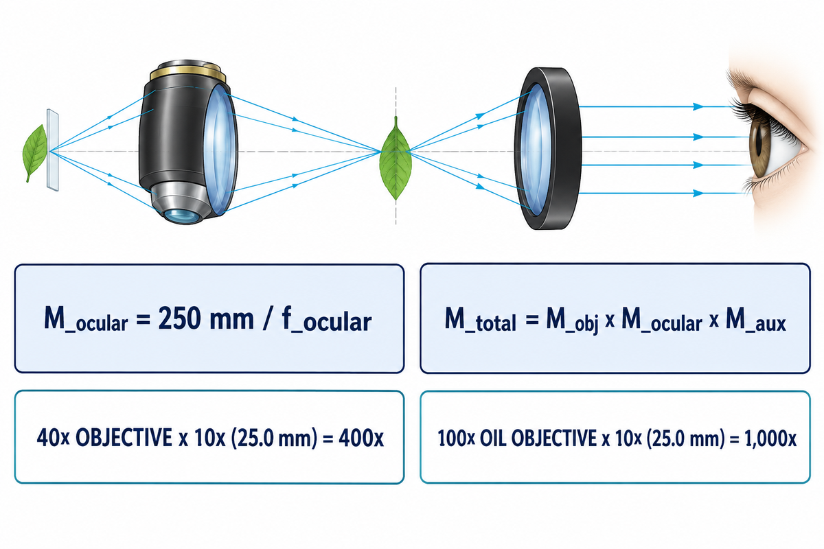
Divide the 250 mm human near-point distance by eyepiece focal length in millimeters to compute ocular power: M_ocular = 250 mm / f_ocular. Next, multiply the power of the objective lens by the magnification of the eyepiece to calculate total visual power. Include any intermediate zoom or auxiliary Barlow in that multiplication.
Optical engineers separate those two stages using the Reference-Distance Split. First, the objective projects a real lateral image inside the head via a finite tube (160 mm DIN or 170 mm JIS) or an infinity tube lens. Second, the eyepiece acts as a compound magnifying glass for the relaxed human eye viewing at infinity. That angular formula references apparent size against the standard 25 cm (250 mm) distinct-vision near point.
Under that 250 mm rule, a 25 mm focal-length tube gives 250 / 25 = 10×, and a 12.5 mm tube gives 20×. The total magnification of the microscope is found by multiplying the magnification of the objective lens by ocular power and any intermediate factor (M_total = M_obj × M_ocular × M_aux). On an Olympus SZX7 Galilean stereo system (7:1 zoom), pairing 0.5× to 2.0× auxiliary lenses with 10× to 30× oculars spans 4× to 336×.
| Stand Configuration | Objective / Zoom Setting | Auxiliary / Tube Factor | Ocular Power (f_ocular) | Total Visual Magnification |
|---|---|---|---|---|
| Compound Scanning | 4x magnification scanning | 1.0× | 10× (25.0 mm) | 40× |
| Compound Low Power | 10× low-dry | 1.0× | 10× (25.0 mm) | 100× |
| Compound High Dry | 40x objective (0.65 NA) | 1.0× | 10× (25.0 mm) | 400× |
| Compound High Dry + Changer | 40× Plan Apo (0.95 NA) | 1.25× intermediate | 15× (16.7 mm) | 750× |
| Compound Oil Immersion | 100x objective (1.25 NA oil) | 1.0× | 10× (25.0 mm) | 1,000× |
| Stereo Zoom + 0.5× Barlow | 0.8×–5.6× zoom body | 0.5× auxiliary | 10× (25.0 mm) | 4×–28× |
| Stereo Zoom + 2.0× Barlow | 0.8×–5.6× zoom body | 2.0× auxiliary | 30× (8.3 mm) | 48×–336× |
What Is the Difference Between Ocular Magnification and Focal Length?
Focal length measures physical convergence distance in millimeters, whereas ocular power is an inverse dimensionless ratio (250 mm / f_ocular). Shorter focal lengths bend rays more steeply and boost angular power. Halving focal length from 25 mm to 12.5 mm doubles eyepiece power from 10× to 20×. One cross-brand rule applies on infinity stands: objective nominal power assumes its matched brand tube-lens focal length (such as 180 mm on Evident/Olympus or 200 mm on Nikon). Mixing infinity objectives across brands shifts actual intermediate magnification by that focal ratio.
Field Number (FN), Field of View, and Why Higher Ocular Power Shrinks Specimen Area
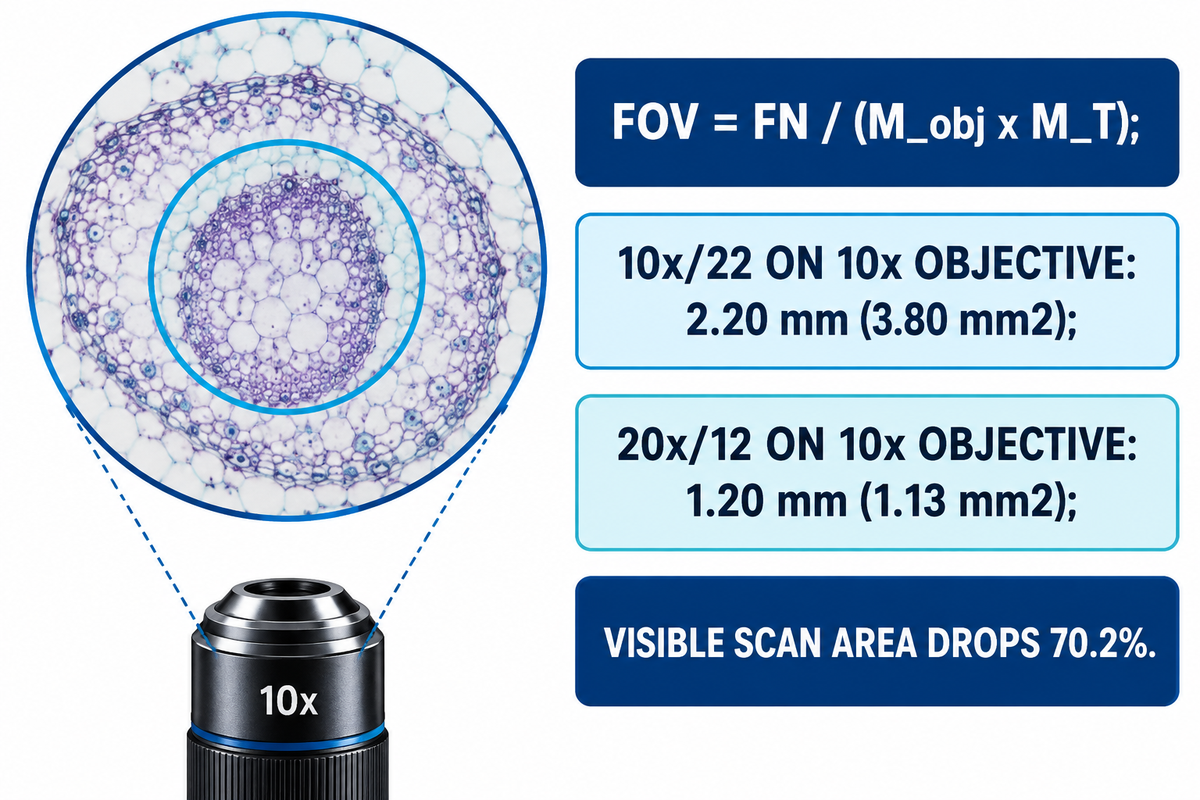
The “Field Number” (FN) of an ocular is the diameter of the circular field stop in millimeters. Divide that Field Number by objective lateral power and any intermediate tube factor M_T to find specimen field of view: FOV = FN / (M_obj × M_T).
In an optical two-stage imaging train, the objective focuses a real inverted projection onto the intermediate image plane. The primary focus, which microscopists call the eyepiece object plane (known as the intermediate image), is located at this projection. A precision metal ring inside the barrel captures this intermediate image and blocks blurred edge rays. Ocular power itself doesn’t enter the field of view (FOV) = Field Number (FN) / M_obj, after Field Number is stated. Its physical stop diameter already accounts for internal lens geometry.
However, higher-power oculars require steeper glass curves that force narrower internal diaphragms. On an Olympus SZX7 stand with a 1× objective, Field Number drops from FN 22 at 10× (27.5–3.9 mm viewfield) to FN 16 at 15× (20.0–2.9 mm). It shrinks further to FN 12.5 at 20× (15.6–2.2 mm) and FN 7 at 30× (8.8–1.3 mm). Circular area scales with diameter squared: A = π × (FOV / 2)². Swapping a 10×/22 tube for a 20×/12 tube on a 10× objective shrinks diameter from 2.20 mm to 1.20 mm. Visible scan area drops by 70.2 percent, falling from 3.80 mm² to 1.13 mm².
Meanwhile, as Evident notes, newer wider field barrels can expand viewable specimen area by up to 40 percent compared to the older, narrower tubes. At low magnification, Nikon MicroscopyU notes that a 2.5× objective with a 10× widefield ocular reveals an 8 mm or wider diameter. Inserting a 1.25× intermediate changer trims image size proportionally. An SWH 10×/26.5 tube with a 40× objective and a 1.25× changer can see 26.5 / (40 × 1.25) = 0.53 mm.
Useful Magnification vs. Empty Magnification: How Numerical Aperture Caps Eyepiece Power
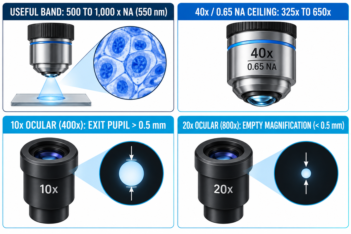
Ernst Abbe’s diffraction limit puts useful magnification between 500 × NA and 1,000 × NA of the objective at 550 nm green light. Going over 1,000 × NA creates empty magnification, making blurry Airy diffraction disks without separating any finer specimen details.
Screen candidate pairings with the Exit-Pupil & Aperture Envelope before ordering high-power tubes. At the 250 mm visual reference distance, human retinal cones (~5 μm pitch) separate points 0.15 mm apart, or 2 arcminutes of angle. Enlarging an objective’s Rayleigh limit (d = 0.61λ / NA) to 0.15 mm takes at least 500 × NA. Exceeding 1,000 × NA never helps increase the resolving power. Worse, it pinches the exit pupil (D_ep ≈ 500 × NA / M_total) below 0.5 mm, projecting tear-film debris and vitreous floaters across the view.
Objective correction quality also limits off-axis contrast well below theoretical limits. Vision Systems Design tested two 5× / 0.14 NA objectives (2.1 μm Rayleigh limit, or 238 lp/mm) on USAF 1951 targets. Both exceeded 20 percent contrast at 360 lp/mm on-axis, yet the budget lens fell to 7 percent contrast at 330 lp/mm off-axis. Adding a 20× eyepiece to a poorly corrected lens magnifies edge blur.
Worked Pairing Example: 10×/22 vs. 20×/12 Ocular on a 40× / 0.65 NA High-Dry Objective
- Abbe Useful Ceiling: 500 × 0.65 = 325x minimum. The maximum useful power is 1,000 × 0.65 = 650x.
- Option A (10× / FN 22 Ocular): Total power is 40 × 10 = 400× (inside the 325× to 650× band). Specimen FOV is 22 / 40 = 0.55 mm (0.238 mm²). Exit pupil stays above 0.5 mm, giving crisp biological cell edges.
- Option B (20× / FN 12 Ocular): Total power hits 40 × 20 = 800× (150× past the 650× ceiling, causing empty magnification). Specimen FOV drops to 0.30 mm (0.071 mm²), and exit pupil shrinks below 0.5 mm.
- Proper Upgrade Path: Raise objective NA instead. Nikon MicroscopyU notes a 25× / 0.65 NA objective with a 10× ocular beats a 10× / 0.25 NA lens with a 25× ocular at 250×.
| Objective Specification | Numerical Aperture (NA) | Useful Total Band (500–1,000 × NA) | Recommended Ocular | Disqualification Boundary |
|---|---|---|---|---|
| 2.5× Plan Scanning | 0.08 | 40×–80× | 10× to 20× (25×–50×) | Suitable at 10× for ≥8 mm field; 30× trims FOV |
| 4× Achromat | 0.10 | 50×–100× | 10× or 15× (40×–60×) | Reject 30× (120× exceeds 100× NA cap) |
| 10× Plan Achromat | 0.25 | 125×–250× | 10× to 20× (100×–200×) | Reject 30× (300× exceeds 250× cap) |
| 20× Achromat | 0.40 | 200×–400× | 10× or 15× (200×–300×) | 20× hits 400× limit; reject 25×–30× |
| 20× Plan Apochromat (High NA) | 0.75 | 375×–750× | 15× or 20× (300×–400×) | 10× under-samples eye acuity; prime 20× candidate |
| 40× High-Dry Achromat | 0.65 | 325×–650× | 10× or 15× (400×–600×) | Reject 20× (800× causes empty blur) |
| 40× Plan Apochromat Dry | 0.95 | 475×–950× | 10× to 20× (400×–800×) | Needs 0.17 mm collar; reject 25×–30× |
| 60× Plan Apo Oil | 1.40 | 700×–1,400× | 10× to 20× (600×–1,200×) | Needs n_d ≈ 1.515 oil; reject 25×–30× |
| 100× Oil Immersion | 1.25 | 625×–1,250× | 10× or 12.5× (1,000×–1,250×) | Reject 15×–20× (1,500×–2,000× floater blur) |
Does Changing from a 10x to a 20x Ocular Lens Improve Microscope Resolution?
No, swapping a 10× eyepiece for a 20x tube will never improve the resolving power of the microscope. Diffraction-limited resolution of the microscope is dependent on wavelength and objective aperture (d = 0.61λ / NA) and keeps magnification and resolution strictly separate. Higher magnification at the ocular helps only when high NA Plan Apochromat or oil immersion objectives out-resolve a 10× viewing angle. One illumination exception applies: the 500–1,000 × NA band assumes 550 nm green light on medium-contrast slides. Short-wavelength 400 nm violet light on high-contrast counting grids tolerates slightly higher maximum magnification at high resolution.
Ocular Lens vs. Objective Lens vs. C-Mount Camera Relay: Where Each Magnification Stage Acts
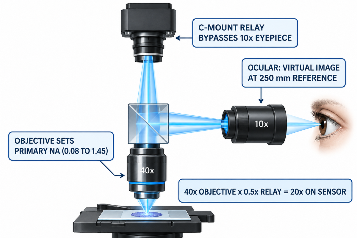
Objective optics, visual oculars, and trinocular C-mount adapters operate at different layers in a microscope system. A trinocular beamsplitter deflects the real image produced by the objective lens before it reaches the ocular tube. The camera port projects to the sensor through a 0.35× to 1.0× relay adapter (M_sensor = M_obj × M_relay).
Mixing up objective and eyepiece paths triggers metrology calibration findings in metallurgy and PCB labs. As the core image-forming component of a compound microscope, the microscope objective gathers diffracted light, sets objective magnification, and produces a magnified image in the intermediate plane. Human observers look through 10× ocular tubes to see a virtual final image. By contrast, a third-port digital camera bypasses glass eyepieces entirely—much like an electron microscope projects onto a detector without optical oculars.
Field mismatches between binocular tubes and C-mount ports surprise rework technicians daily. On a trinocular stereo soldering stand using WF10X/20 oculars and a 0.5× Barlow lens, eyepieces show a 55 mm working circle. Yet the camera feed captures only 28 mm across, cropping roughly 75 percent of the visual area. A 1/2.33-inch CMOS chip has a 7.66 mm diagonal. Dividing 7.66 mm by a 0.5× C-mount reduction lens samples a 15.32 mm diagonal of the intermediate circle. Pairing a larger 8.86 mm chip (Sony IMX678) with a 0.3× reducer demands a 29.5 mm image circle, causing dark vignetting inside a 23.2 mm port.
In matching the sensor size to a C-mount reduction, one avoids both severe corner cropping and corner shadow artifacts. Factory C-mount relays—such as Olympus SZX7 0.5× (#11-123) and 0.63× (#11-122) adapters, listed at $1,170.00 each at Edmund Optics—fit 1/2-inch and 2/3-inch sensors cleanly. Dedicated photomicrography projection lenses (1× to 5×) also serve large sensors and cannot be used for direct eye viewing.
| Optical Parameter | Objective Lens | Ocular Lens (Eyepiece) | Trinocular C-Mount Relay |
|---|---|---|---|
| Image Type Produced | Real inverted projection at intermediate plane | Virtual image at infinity (250 mm reference) | Real projection focused onto flat CMOS sensor |
| Typical Power Factor | 2.5× to 100× (compound); 0.5×–2.0× aux | 10× standard (5× to 30× commercial range) | 0.35×, 0.5×, 0.63×, or 1.0× relay |
| Sets Diffraction Resolution? | Yes — sets primary NA (0.08 to 1.45) | No — enlarges viewing angle for retina | No — matches Airy disk to pixel pitch |
| Field Limiting Stop | Rear aperture / tube-lens clear bore | Circular internal diaphragm (FN 6–26.5 mm) | Sensor diagonal divided by relay factor |
| Calibration Standard | Lateral power engraved for matched tube lens | Stage micrometer vs. eyepiece graticule | Micrometer scale bar in pixels (μm/pixel) |
Why Doesn’t a Trinocular Microscope Camera Use the 10x Ocular Lens Magnification?
A trinocular prism splits the beam below the viewing head. This sends the objective’s intermediate image up the C-mount port without touching either 10× eyepiece. Therefore, objective lens magnification only multiplies the C-mount adapter factor. A 40× objective with a 0.5× C-mount relay projects 20× onto the sensor, never 400×. Burn a calibrated micrometer scale bar (such as 50 μm) onto saved images instead of writing “400×”, because monitor size alters the apparent display scale.
Eyepiece Optical Designs, ISO 9345 Barrel Sizes, Eye Relief, and Reticle Calibration
Internal diaphragm location, ISO barrel diameter, and eye-point height determine replacement eyepiece fit and reticle support. For positive Ramsden and Kellner barrels and other recent widefield barrels, the focal stop is positioned before the field lens for drop-in reticles. Standardized outer barrels measure 23.2 mm or 30.0 mm under ISO 9345:2019 (confirmed in 2024).
Negative Huygens oculars mount an internal diaphragm between two plano-convex lenses, preventing simple user reticle drops. By contrast, positive Ramsden tubes move that stop below the field lens. Modern Kellner, widefield, and plan-compensating barrels add cemented doublets to magnify the image flatly across 22 mm to 26.5 mm fields. Those doublets use crown and flint achromatic lenses and matching optical glasses to cancel lateral color fringes.
Broadband coatings on all air-glass surfaces of multi-element barrels are equally important. Applying multi-layer anti-reflective coating principles on optical glass cuts per-surface reflection below 0.5 percent. Low reflectance prevents ghost flare from masking faint details in an image lit by the substage condenser lens. When a lens magnifies angles past 35 degrees, hybrid doublets or aspheres curb pincushion distortion. U.S. Patent 6,282,030 B1 reports a 10× wide-angle eyepiece reaching over 30 mm eye relief and under 2 percent distortion, beating 5–10 percent distortion in all-spherical 10× tubes.
Mechanical and ESD specs also govern production benches. ISO 9345 assigns 23.2 mm barrels to standard compound heads and 30.0 mm barrels to stereo and widefield research stands. On electronics lines, the Motic SMZ-171 WF10X/23 ESD tube ($124 catalog) accepts a 100-division / 10 mm micrometer disc. Likewise, 24 mm Evident WH discs and 27 mm Edmund crosshairs ($220.00) require stage-micrometer calibration at each stop across the magnification range and working distance.
| Eyepiece Design Family | Lens Grouping | Field Diaphragm Plane | Drop-In Reticle Compatibility | ISO 9345 Barrel & Eye Relief |
|---|---|---|---|---|
| Huygens (Negative, H) | 2 plano-convex crown lenses | Internal (between eye and field lens) | Not suitable for user drop-in discs | 23.2 mm tube; 6–10 mm relief |
| Ramsden (Positive, R) | 2 plano-convex lenses (convex inward) | External (below lower field lens) | Suitable; sharp reticle, mild fringe | 23.2 mm tube; 8–12 mm relief |
| Kellner / Achromatic Widefield | Field lens + crown/flint eye doublet | External front focal stop | Recommended (19 mm–21 mm discs) | 23.2 or 30.0 mm; 14–18 mm relief |
| Plan-Compensating High-Eyepoint | 4–7 elements (multi-doublet AR) | External lower retaining ring | Recommended (24 mm–27 mm discs) | 23.2 or 30.0 mm; 20–25 mm eyepoint |
How Do You Use a Microscope Ocular Lens If You Have Astigmatism or Wear Glasses?
Keep your prescription eyeglasses on, fit high-eyepoint (H or HE) 10× oculars with 20–25 mm eye relief, and fold down the rubber eyecups. Standard oculars give only 8–10 mm relief, which vignettes the outer field with spectacles on. Remember one optical limitation: the -8 to +2 diopter collar on an ocular lens allows for myopia and hyperopia. Cylindrical astigmatism can’t be corrected with spherical diopters at any lens magnification or magnification powers.
Flat Optical Windows, Reticle Substrates, and Precision Glass Roles Around Microscope Optics
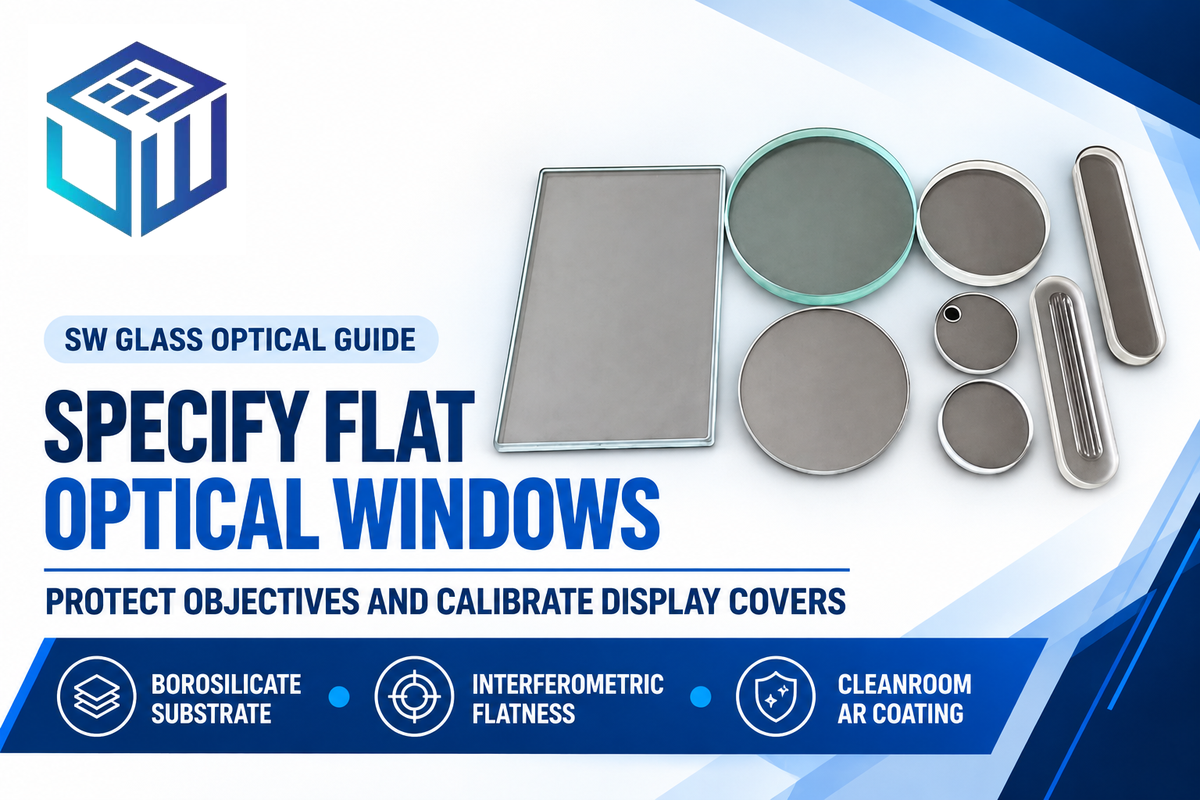
Curved refractive lens elements and flat protective microscope glass come from separate manufacturing lines. Spherical optical shops grind curved crown and flint lenses that set microscope magnification. Precision flat glass fabricators like Dongguan Saiwei Glass Co. Ltd. CNC-machine protective windows, reticle blanks, stage plates, and display covers.
Even zero-power flat glass degrades wavefront quality when thickness or flatness drifts. According to RP Photonics’ microscope objective guide, dry objectives above 0.75 NA assume a 0.17 mm (170 μm) cover slip. At 0.95 NA, a 10 μm thickness error visibly blurs the image formed without collar adjustment. Ordinary soda-lime glass ahead of soldering or laser objectives adds roller-wave distortion and ~8 percent Fresnel reflection loss. The larger the image magnification of a microscope, the faster stray reflections degrade the image created from the image of an object.
Instrument OEMs shield front optics and sensor ports with custom flat optical glass windows and precision substrates cut from low-expansion borosilicate glass substrates. For heated stages, autoclaves, and laser shields, engineers also check borosilicate glass thermal softening and operating limits before chemical strengthening. At Dongguan Saiwei Glass Co., Ltd. (SW Glass), 5-axis CNC profiling holds ≤0.01 mm tolerances and diamond sawing holds ≤0.05 mm across BK7, crown, borosilicate, and fused silica sheets. Precision polishing achieves up to 20-10 scratch-dig quality and λ/10 flatness with surface roughness Ra < 0.2 μm, while ion-exchange strengthening reaches CS ≥ 600 MPa and DOL ≥ 20 μm. Multi-layer AR coatings inside Class 1000 cleanrooms deliver ≥98 percent light transmission, keeping the image of the object sharp in industrial microscopy. Scope boundary: SW Glass fabricates flat and custom-shaped windows, stage plates, and HMI touch covers, not curved spherical eyepiece lenses or raw glass melt.
| Specification Item | Target Parameter to Call Out on Drawing | SW Glass Verified Capability & Inspection Basis |
|---|---|---|
| Substrate Glass Family | BK7, borosilicate, aluminosilicate, fused silica, or crown glass | Batch-traceable sheet certificate matched to optical band |
| CNC Contour & Sawing | Nominal thickness (mm), outer profile, bevel, and datum | ≤0.01 mm 5-axis CNC profiling; ≤0.05 mm diamond sawing |
| Flatness & Strengthening | Target interferometric flatness, roughness, and impact spec | Flatness to λ/10 (@632.8 nm), Ra < 0.2 μm; CS ≥600 MPa, DOL ≥20 μm |
| AR / AF / ITO Coating Stack | Target wavelength band, multi-layer AR, AF, or ITO sheet resistance | ≥98 percent light transmission AR; AF angle ≥110°; ITO 3–8000 Ω/sq |
| Clear Aperture & Cosmetics | Optical zone vs. silkscreen border (±0.15 mm) and scratch-dig | Up to 20-10 scratch-dig polish; Class 1000 cleanroom & ISO 9001:2015 |
| Quantity & Sample Scope | Prototype count, spectrophotometry report, and tray pack | Pricing requires drawing review (request quote); 24-hour DFM review |
Microscopy Optics Outlook: Hybrid Digital Inspection, ISO 18221 Display Standards, and Durable Protective Coatings
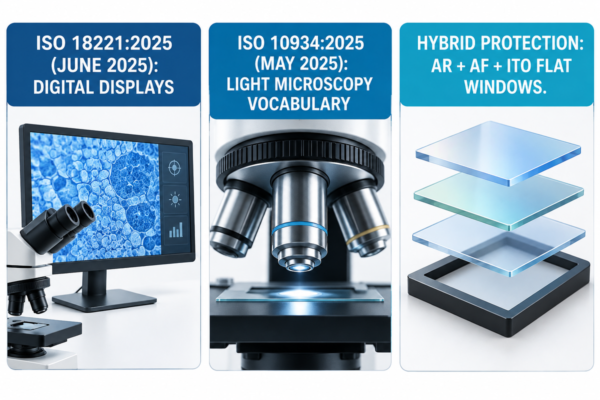
International microscopy standard revisions in 2025 were attributable to factory shifts from eyepiece-only benches to hybrid trinocular and monitor workstations. As a result, quality engineering teams now set 10× visual ocular barrel parameters in conjunction with pixel-calibrated digital magnification, and replaceable protective windows across production facilities.
“This document specifies the minimum information to be provided to the user by the manufacturers of microscopes with digital displays regarding imaging performance.”
ISO 18221:2025, Microscopes, Microscopes with digital imaging displays (Edition 2, June 2025)
Released in June 2025 to replace the 2016 edition, ISO 18221:2025 covers every non-confocal digital microscope and display-equipped stand. It cross-references visual eyepiece terms to ISO 10934:2025 (Vocabulary for light microscopy, May 2025) and ISO 8039. Multi-site QA teams align SOPs by logging both visual ocular specs (such as 10×/22 on ISO 9345 tubes) and micrometer scale bars on 4K computer monitor feeds.
Meanwhile, SMT flux inspection, laser rework, and medical and surgical microscopy optical glass assemblies endure harsher wipe-down solvents and ESD rules. Instead of subjecting costly front fluorite lenses to solder spatter, OEM heads fit replaceable flat windows. Combining double-sided AR, oleophobic AF, and ITO static-bleed layers keeps inspection optics clear.
Frequently Asked Questions
1. What do the 4x, 10x, 40x, and 100x markings mean when paired with a 10x ocular lens?
Those four barrel engravings represent the lateral powers for each objective on a revolving nosepiece as follows: 4× scanning, 10× low power, 40× high-dry, 100× oil-immersion.
Multiplying each objective power by a standard 10× eyepiece yields a total visual power of 40×, 100×, 400×, and 1,000×. This is assuming a standard 1.0× observation tube factor with no auxiliary intermediate changers.
2. How can you find the magnification of an unmarked microscope ocular lens?
Project a distant collimated light beam through the removed ocular lens onto white card stock and measure the sharp focal distance f in millimeters.
Divide 250 mm by the measured focal distance (M = 250 / f). Alternatively, check the apparent stage-micrometer divisions against a calibrated 10× reference eyepiece, mounted on the same objective.
3. When does switching from a 10x to a 15x or 20x ocular lens actually help?
Upgrading to a 15× or 20× eyepiece helps only when 10× leaves total visual power well below the objective’s 1,000 × NA diffraction ceiling.
Valid applications include high-aperture Plan-Apochromat objectives, for example, a 20x/0.75 NA. Higher power tubes also work well with low-zoom stereo soldering stands that maintain tool clearance and allow fine reticle vernier alignment.
4. Is a microscope ocular lens convex or concave?
A visual ocular acts as a positive (convex) magnifying assembly. In widefield barrels, designers cement a convex crown element to a concave flint lens to get rid of color fringes.
5. Why does a 100x objective lens require immersion oil when used with a 10x ocular lens?
Immersion oil (n_d ≈ 1.515) bridges the 0.17 mm coverslip and front lens via glass refractive index matching across optical interfaces.
Oblique diffracted rays strike the cover glass at the interface and suffer total internal reflection in air (n = 1.00) and consequently, the dry aperture is limited to 0.95 NA. Oil unlocks 1.25 to 1.45 NA. Thus, 1,000× visual power (100× objective × 10× ocular) resolves sub-micron structures rather than empty blur.
6. Can you swap 10x ocular lenses between different microscope brands?
Yes, when both heads use the same ISO 9345 barrel diameter (23.2 mm or 30.0 mm) and neutral aberration correction. Never install older lateral-color compensating tubes onto modern color-free infinity stands.
7. How do you calculate total magnification on a stereo zoom microscope with 10x eyepieces?
Multiply eyepiece power by the zoom dial setting and any screw-on front auxiliary Barlow factor: M_total = M_ocular × M_zoom × M_aux.
For example, a 0.7× to 4.5× zoom body with 10× eyepieces yields 7× – 45× natively. With a 0.5× lens added, the power halves to 3.5× – 22.5×, and clearance doubles. On the other hand, a 2.0× lens at the front doubles visual power to 14× – 90×.
Specifying Custom Protective Optical Windows or Microscope Display Cover Glass?
Send your 2D/3D window drawing, target AR/AF/ITO coating band, thickness tolerance, and flatness spec to Dongguan Saiwei Glass (SW Glass). Our optical engineers review custom flat glass drawings and return DFM feedback with first-article inspection scope before tooling. We perform pre-production tooling review.
Why Our Optical Glass Team Wrote This Guide
Reviewed by the optical engineering team at Dongguan Saiwei Glass Co., Ltd. (SW Glass) under ISO 9001:2015 and Class 1000 cleanroom metrology protocols. Calculations assume the 250 mm human reference viewing distance, λ = 550 nm green illumination, and ISO 9345 tube interfaces. Verify brand tube-lens focal lengths and stage-micrometer calibration on your stand before releasing inspection SOPs.
Related Articles
References & Sources
- 26.4 Microscopes, College Physics 2e OpenStax, Rice University.
- 2.9: Microscopes and Telescopes, University Physics Vol. 3 Physics LibreTexts / OpenStax.
- Microscopes, RP Photonics Encyclopedia Dr. Rüdiger Paschotta, RP Photonics.
- Choosing the Correct Microscope Objective: Numerical Aperture and Other Key Factors Cory Boone, Vision Systems Design, Dec. 2024.
- ISO 9345:2019, Microscopes: Interfacing dimensions for imaging components ISO, confirmed Oct. 2024.
- US6282030B1, Eyepiece assembly using plastic aspheric element J. M. Hall, U.S. Army / USPTO.
- Microscope Objectives, RP Photonics Encyclopedia Dr. Rüdiger Paschotta, RP Photonics.
- ISO 18221:2025, Microscopes with digital imaging displays ISO, Edition 2, June 2025.
- ISO 10934:2025, Vocabulary for light microscopy ISO, Edition 2, May 2025.