Get in Touch with Saiweiglass



Updated October 2026
The cover glass hole edge distance is the narrowest clear distance between the edge of the hole and the finished outside edge of the glass. Center-to-edge dimension measures something different. Before approving a camera opening, mounting hole or sensor aperture, check three things: the dimension definition, the smallest remaining ligament after tolerances, and the manufacturing route that will create it.
A drawing may show sufficient space and leave the supplier uncertain which surface to measure. It may also pass dimensional inspection without proving the finished assembly will withstand loads. The following drawing checks separate those decisions for a custom cover glass, with a worked example you can replace with your own dimensions.
Key takeaway
Calculate the glass that remains, then ask the fabricator and design authority whether that geometry is acceptable for the specified material, process and assembly.
Measure hole edge distance from the correct feature
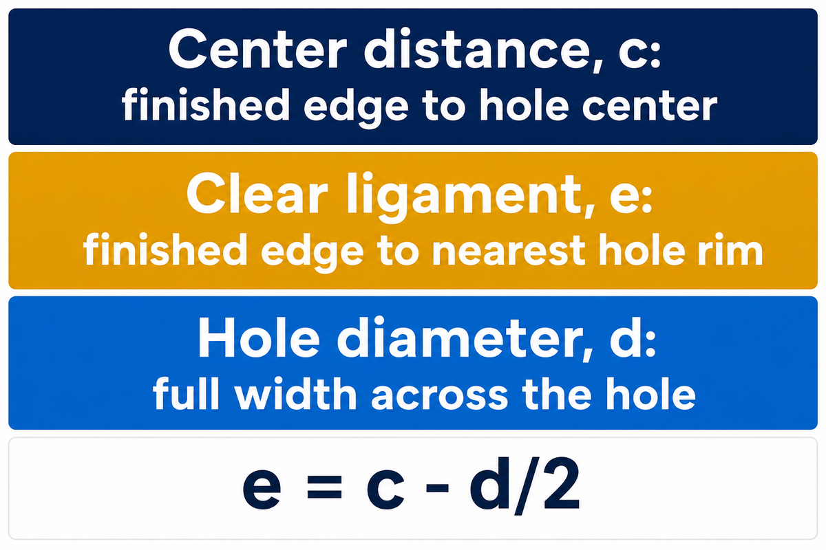
To measure the edge distance of a hole, start from the nearest edge of the hole and measure to the finished glass edge. For a drawing with a circular hole, center-to-edge distance is measured from the center of the hole. Confusing the two measures consumes half the hole diameter before any tolerances are considered. Therefore, the plan for the inspection must define the intended measurement.
According to Viracon’s fabrication guidance, edge distance is defined by the nearest point of the hole rim. For a round hole next to a straight edge, the remaining ligament (e) is given by the following equation: e = c – d/2, where c is the perpendicular center-to-edge distance and d is the finished diameter of the hole. The circle’s radius connects the two dimensions.
Say a mechanical designer places a note on a preliminary panel drawing stating that a sensor opening is “8 mm from edge.” The buyer sends that drawing for a quote, and the supplier assumes the note places the hole center. If the hole has an 8 mm diameter, then 4 mm of glass remains. If the designer intended an 8 mm clear ligament, the center belongs 12 mm from the edge. Not including the diameter and the center coordinate based on a datum is likely to cause confusion and lead to errors in tooling, inspection and approval of samples.
Drawing mistake to avoid: Measuring to the black printed border should be avoided. Ink artwork does not define the structural glass boundary. If a buyer needs a smooth exterior appearance, the black border and the actual glass edge should be drawn as separate features.
Quick Specs: illustrative geometry only
- 12mm center-to-edge distance
- 8mm finished hole diameter
- 8 mm nominal clear ligament
- Straight finished edge; no strength acceptance implied
A 12 mm center distance and an 8 mm diameter leave an 8 mm nominal ligament beside a straight edge. Calling either dimension “edge distance” without a definition invites a different interpretation. Put the finished glass outlines, hole diameter, and measurement references on the same controlled drawing.
Calculate the minimum remaining glass with tolerances
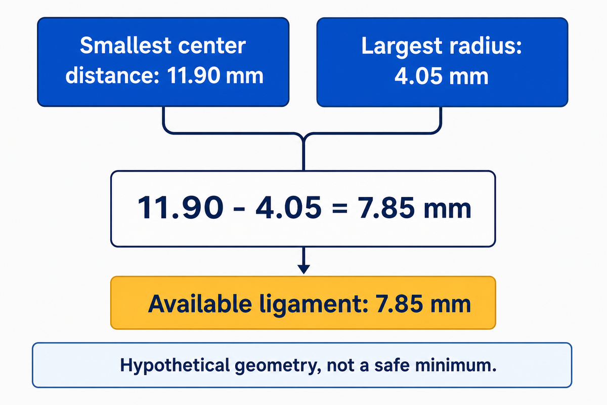
The smallest available ligament can be calculated using the closest allowable hole location and the largest allowable hole radius. That describes the geometry at the tolerance limits. It becomes an acceptance check only after a separate, applicable minimum has been agreed for the material, manufacturing process and intended assembly.
How is cover glass hole edge distance calculated?
For a circular hole measured directly from its center to the actual finished straight edge, it’s emin = cmin – dmax/2. The minus side of c is used for bilateral location and the plus side of d is used for diameter. The largest internal hole is the least-material size, thus we can’t call it the maximum-material hole.
Suppose a drawing controls c at 12.00 ± 0.10 mm and d at 8.00 ± 0.10 mm. Nominally, 12.00 − 8.00/2 leaves 8.00 mm. At the unfavorable limits, the center is 11.90 mm from the finished edge and the hole is 8.10 mm across. Its radius is therefore 4.05 mm, leaving 7.85 mm. A buyer comparing a quotation against an 8.00 mm minimum would see a 0.15 mm shortfall, even though the nominal picture looks correct. Moving the center 0.15 mm farther from the edge would recover that geometric difference with unchanged tolerances; the revised feature would still need manufacturing and application review.
3-Dimension Ligament Worksheet
A tolerance worksheet separates the nominal ligament from the smallest permitted remaining glass beside a straight edge.
| Worksheet field | Example entry | Meaning or limitation |
|---|---|---|
| Center distance, c | 12.00 mm | Directly to the actual finished straight edge |
| Location tolerance | ±0.10 mm | Bilateral example, not a position-tolerance zone |
| Smallest center distance | 11.90 mm | 12.00 − 0.10 mm |
| Hole diameter, d | 8.00 mm | Finished circular hole |
| Diameter tolerance | ±0.10 mm | Largest hole reduces the ligament |
| Largest diameter | 8.10 mm | 8.00 + 0.10 mm |
| Largest radius | 4.05 mm | 8.10 ÷ 2 |
| Nominal ligament | 8.00 mm | 12.00 − 8.00/2 |
| Minimum available ligament | 7.85 mm | 11.90 − 4.05 mm |
| Approved minimum | Enter the agreed value | Requires separate process and design evidence |
Source basis: author-derived arithmetic using the nearest-rim definition in Viracon’s hole guidance. Every input above is hypothetical. A drawing with a different datum system needs a different tolerance chain.
We don’t subtract an outside-edge tolerance twice. If c already controls distance to the actual finished edge, the example accounts for that edge relationship. If both features are located from a separate datum, include the permitted relative motion. A diametrical position callout also requires its own interpretation and can’t replace the ±0.10 mm entry.
Engineering Note
The example’s 12.00 ± 0.10 mm center dimension and 8.00 ± 0.10 mm diameter establish a 7.85 mm minimum available ligament. They are not tolerances prescribed by ASTM C1422/C1422M-26. Its public scope excludes end-use performance, so keep geometric acceptance separate from assembly validation.
The result, 7.85 mm, is an available dimension, not a universal minimum edge distance for a glass hole. If a quoted design needs more material, compare moving the opening, reducing its size or changing the interface before buying tighter tolerances. The accepted drawing must state which change actually provides the needed material.
Match hole-spacing rules to the strengthening process
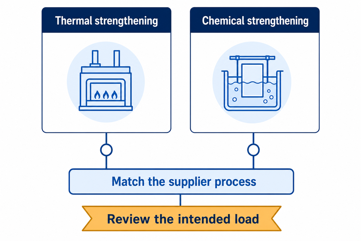
For the actual strengthening route and supplier process, select hole-spacing rules. Thermal fabrication tables can provide a useful comparison, but they do not establish a universal limit for thin chemically strengthened glass. Material composition, thickness, feature geometry and the intended load still need to be linked to the proposed part.
Viracon has stated that the minimum rim distance is 6 mm or twice the glass thickness, whichever is greater. Its separate between-hole rule uses the greater of 10 mm and twice the thickness, and its corner guidance uses 6.5 times thickness from the corner tip to the nearest hole rim when the corner is 90° or more. Those figures sit within that supplier’s thermal-fabrication guidance.
The distinction also appears in primary references. ASTM C1048-25 addresses heat-strengthened and fully tempered flat glass in its stated scope. ASTM C1422/C1422M-26 covers chemical strengthening, including electronic applications, and classifies products using surface compression and compression depth.
A more extensive comparison of chemical strengthening and thermal tempering shows which process to include in the material callout.
“This specification does not purport to address end-use performance.”
A certification of a strengthening class does not answer every hole-strength question. In Efferz, Schuler and Siebert’s near-edge-hole study, the authors distinguish thermal production spacing from structural strength. Their tests concern 5 mm, 8 mm and 12 mm thermally toughened specimens; the findings don’t validate a thin chemical cover design.
For a supplier rule expressed as the greater of 6 mm and 2t, a 4 mm thickness gives 8 mm under that rule. The arithmetic doesn’t transfer the rule to another glass family. Be certain which process and what validation support the offered spacing before accepting a smaller value.
Plan the hole-making sequence before strengthening
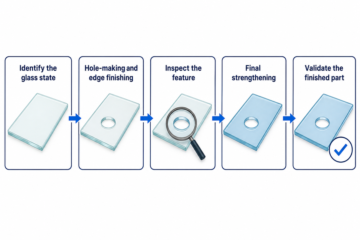
Plan the standard glass drilling, edge finishing and feature inspection prior to the final strengthening process. A late opening may require the supplier to change the entire process route rather than add a single machining step. Verify the process on the drawing review, especially if the part has coatings, printed areas, or bonding surfaces.
How to cut a hole in glass without breaking it?
For an industrial cover, start with the state of the material and a qualified manufacturing route. The abstract of ASTM C1048-25 states drilled holes and other fabrication processes are performed prior to heat strengthening or tempering. Normal drilling of a finished thermally tempered panel is not a valid drawing change. Review the cover glass manufacturing process before fixing downstream coating and assembly dates.
More specific requirements warrant narrower descriptions. In Patent US9481598B2, laser cutting of strengthened glass is described; the record lists Smart Window Inc Ltd as the current assignee with a caution regarding listing accuracy. A cutting patent doesn’t mean a supplier can routinely drill a given finished cover. It does not establish SW Glass ownership or equipment.
- Identify the glass state. Record the composition and whether strengthening has already occurred.
- Review the feature route. Agree hole-making, edge finishing and inspection before final strengthening.
- Validate the finished part. Include the later coating, bonding and assembly conditions that affect acceptance.
If a promise is made to purchasing that a laser can solve a last-minute change, request results from the actual material and feature. A clean demonstration cut is useful evidence of feasibility; it does not settle production repeatability or the finished assembly’s performance.
Review adjacent holes, slots and rounded corners
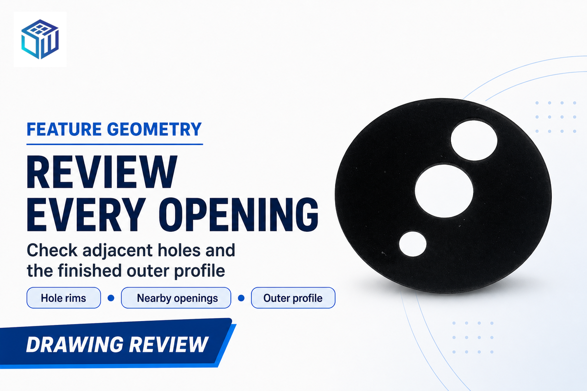
Measure the shortest remaining material path around each opening, including adjacent holes and the outside profile, before assessing the feature. Not all features, such as a slot, will allow a straight-edge determination. Geometry-specific checks should be performed before a determination is accepted.
Hole-Feature Ligament Worksheet
A geometry worksheet separates the nominal ligament from the shortest remaining glass around each hole or edge.
| Feature type | Measure or inspect | Limit of the simple formula |
|---|---|---|
| Round through-hole, straight edge | Perpendicular center distance and finished diameter | Applies only with a defined tolerance chain |
| Two round holes | Center spacing minus both radii | Center spacing is not clear glass width |
| Hole near a square corner | Both edges and the corner region | One edge measurement can miss the critical region |
| Hole near a rounded outer corner | Shortest rim-to-profile path | Do not measure to a theoretical sharp corner |
| Long slot | Both side ligaments and end radii | A single equivalent diameter loses geometry |
| Rectangular aperture | Side widths and internal corner radii | Local corner behavior needs separate review |
| Edge-opening notch | Remaining arms, root radius and finish | A closed-hole model does not describe the notch |
| Countersunk or chamfered hole | Largest surface opening and remaining section | The cylindrical bore alone may miss removed material |
| Coated or laminated opening | Each relevant glass boundary and layer interface | Ink or adhesive boundaries are not glass edges |
The information is synthesized from separate directions for holes, corners, and features that aren’t circular from Viracon, with limitations stated in the Efferz study. The matrix provides the basis for inspection, not to establish dimensions.
What’s meant by a supplier’s “hole spacing” may be rim-to-rim clearance, and what’s stated on the drawing may be centers. Resolve these discrepancies in writing. If an opening is located by a rounded corner, asking for the distance across the straight side leaves the rounded profile unverified; an actual drawing should be provided rather than a screenshot of a dimension.
Two 8 mm circular holes on 12 mm centers leave 4 mm of nominal glass between their rims. That example illustrates the difference between center spacing and clear width. Position and diameter tolerances can reduce it further, and the supplier must review the resulting inter-hole ligament for the specified process.
Inspect the ligament and the hole edge separately
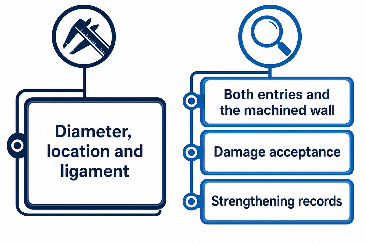
Inspect dimensions and edge condition as separate acceptance characteristics. Dimensions and ligament measurements show if the part is geometrically correct. Chip limits, cracks and strengthening state evidence address various risks, and a tight tolerance shouldn’t replace a defined quality check on the machined edge.
Hof and Abou Ziki’s micro-hole drilling review describes cracking associated with mechanical drilling, particularly at the exit. A Light Conversion technical feature in Photonics Spectra discusses why via dimensions can conceal different stress conditions. Those via processes differ from cover-glass production, but the distinction between measured size and process damage is useful.
The strengthening process also raises questions about the material state. Egboiyi and Sain’s 2020 research abstract links fracture resistance to the relationship between initial flaw depth and the stress profile. A supplier should provide strengthening evidence and application checks in accordance with the requirements. The study doesn’t provide a limit for edge distance of the hole in the drawing.
Staff should agree on how inspections, viewing and treatment of defects will be done for both faces.
Buyer’s requests for “no chips” should define how requirements will be measured and documented. The cover glass testing overview can help organize the broader discussion, while the purchase drawing should carry the specific agreed criteria. The requirements should be reflected on the buyer’s drawing.
- Record diameter, location and ligament against the drawing.
- Inspect both hole entries and the machined wall using the agreed method.
- Keep damage acceptance and strengthening records identifiable with the inspected part.
A hole measuring 8.00 mm can meet its dimension requirement while still requiring a separate decision regarding edge quality. In the case of a 12.00 mm center distance, record the size, location and ligament, along with the agreed inspection for damage. A smooth rim or a nominal dimension doesn’t guarantee the finished strength of the assembled part.
Check mounting loads before accepting a narrow ligament
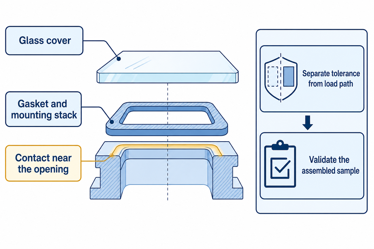
Review how the assembly loads the glass around the opening. Factors such as fitting contact, support location, preload and movement of the housing can affect the loading of a narrow ligament. In validation, consider the service conditions, particularly if the load is sustained. A dimensional fit check describes neither the operational loads nor long-term reliability of the product.
Suppose a buyer approves a cover because its sensor hole clears the housing boss during a bench fit check. Production then completes the assembly with the specified gasket and fastener, and the mounting stack applies a load near the opening. A designer may prefer moving the boss while purchasing may want to retain the housing tool and tighten the tolerance on the glass clearance. Those changes solve other problems. A smaller dimensional spread won’t, by itself, eliminate contact load. Before producing the final part, compare the changed interface and inspect an assembled sample under the agreed conditions. That may prevent paying for precision that doesn’t address the actual problem.
The abstract of Stephen Freiman’s NIST publication describes delayed failure due to environmental and stress effects on slow crack growth in glass. It doesn’t provide a method to calculate cover glass life. In the validation plan, identify the environment and duration to which cover glass will be subjected and relate any impact requirement to the tested cover glass assembly.
- Check contact near the opening with the complete mounting stack.
- Separate a tolerance problem from a load-path problem.
- Agree application-relevant loading and environmental checks before release.
Release the drawing with a machinability review
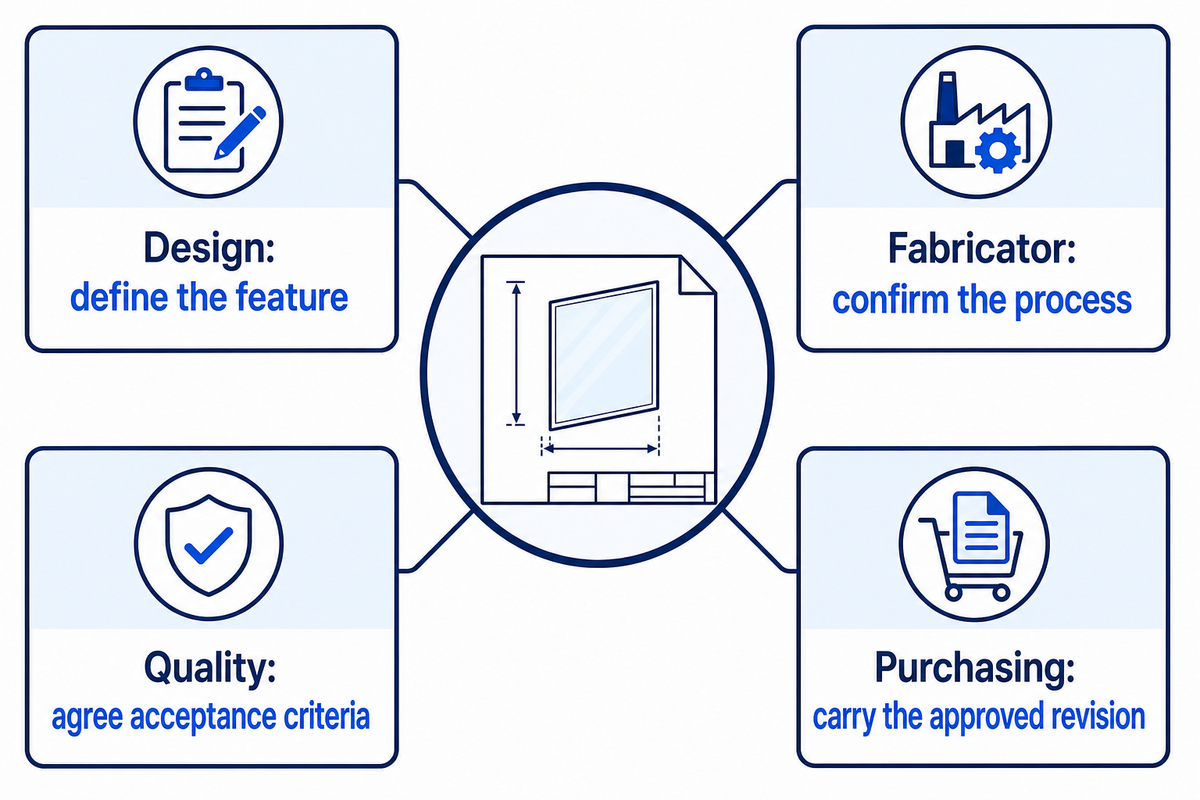
Release the drawing once the design owner, fabricator and quality team agree on the feature definition, the feasible process, and the acceptance criteria. Purchasing should carry this agreement into the order revision. Use the matrix below to expose unresolved decisions before a nominal dimension becomes a commitment to produce to that dimension.
Hole-Feature Release Matrix
This matrix assigns a decision owner, acceptance condition and next action to each unresolved hole-feature question.
| Decision | Lead owner | Release condition | If unresolved |
|---|---|---|---|
| Glass identity | Design engineer | Composition, thickness and material state specified | Do not approve a generic glass substitution |
| Measurement definition | Design engineer | Rim, center and finished outline distinguished | Clarify the datum and dimension callouts |
| Worst-case ligament | Mechanical engineer | Tolerance chain evaluated without double counting | Revise geometry or obtain a feasible tolerance proposal |
| Nearby features | Manufacturing engineer | Slots, corners and adjacent openings reviewed | Review the complete profile |
| Process sequence | Fabricator | Hole-making and finishing linked to strengthening | Reassess any late feature change |
| Edge quality | Quality engineer | Measurable defect criteria and method agreed | Define inspection before accepting samples |
| Strengthening evidence | Quality engineer | Required material-state records identified | Avoid inferring strength from appearance |
| Assembly performance | Product design owner | Relevant loads, duration and environment validated | Keep application approval open |
| Commercial release | Buyer | Quote, samples and order share the approved revision | Resolve exclusions before production commitment |
Source basis: Synthesis of the public chemical strengthening scope, machining literature, and the defined worked example. The matrix is a drawing review aid and won’t replace part-specific engineering and/or tests.
If price or lead time improves only by relaxing a requirement, identify that requirement explicitly. A quote excluding edge inspection isn’t directly comparable to one including it. Carry these decisions into the broader cover glass drawing checklist without duplicating the complete quotation package here.
SW Glass publicly offers custom glass drilling. Send a controlled drawing, state of the material, and the state of the intended assembly, for a machinability review of your custom cover glass specification. Have the supplier quote identify the agreed geometry and process and the remaining validation activities.
Frequently Asked Questions
Can you drill tempered glass?
Conventional holes should be made before thermal tempering.
The public ASTM C1048-25 abstract places drilled holes and other fabrication before strengthening or tempering within its scope. A late opening in a finished tempered panel requires a manufacturing review and may require a replacement part. Specialized laser-cutting research or patents do not establish an ordinary drilling procedure for your cover, its hole geometry or its finished assembly.
Can you drill laminated glass?
A laminated-glass opening needs review of the complete layer construction.
Tell the fabricator the glass types, strengthening state, layer thicknesses and interlayer, together with the required finished opening. Don’t assume that permission to machine an annealed ply also permits drilling a finished laminate containing tempered plies. Ask how the proposed route addresses alignment between layers, exposed interlayer edges, damage acceptance and later assembly. A simple single-ply ligament calculation can’t settle those questions.
Does thicker cover glass always permit a hole closer to the edge?
Greater thickness does not automatically permit a smaller hole-to-edge ligament.
Some thermal-fabrication rules increase the required spacing with thickness. Chemical strengthening also depends on the specified material state and damage conditions, rather than thickness alone. A thicker replacement may change the manufacturing route or assembly contact. Compare the proposed glass, opening and support arrangement together, then obtain the supplier’s applicable dimensional limits and the design owner’s performance acceptance before revising the drawing.
Does the printed border count as the glass edge?
The structural ligament ends at the physical glass edge.
Dimension printed artwork separately. A black border may hide an opening visually, but its boundary doesn’t add glass between the hole and the outside profile.
What should I change if the supplier rejects the available ligament?
Identify the supplier’s limiting condition before changing the design.
A dimensional shortfall may be resolved by moving the opening or reducing its size, provided the interface still works. An edge-quality problem may require another feature-making or finishing route. An assembly-load problem may call for a different support or mounting arrangement. Ask the supplier to separate those reasons instead of requesting a smaller minimum without a changed process. Compare the effect on tooling, inspection and sample approval, then issue a revised drawing. Keep the old and new revisions identifiable so a quotation for one geometry isn’t mistaken for acceptance of the other.
Technical basis: public supplier guidance, standard scopes and research reviewed in October 2026. Dimensional examples are hypothetical. No private production trials, client yield data or universal safe hole-spacing value are claimed.
References & Sources
- ASTM C1048-25: heat-strengthened and fully tempered flat glass ASTM International, public abstract and scope.
- ASTM C1422/C1422M-26: chemically strengthened flat glass ASTM International, public scope.
- Experimental determination of the strength of toughened glass near edge holes Lena Efferz, Christian Schuler and Geralt Siebert; Glass Structures & Engineering, republished by Glass on Web.
- US9481598B2: laser cutting strengthened glass patent record, Google Patents.
- Micro-Hole Drilling on Glass Substrates, A Review Lucas A. Hof and Jana Abou Ziki; Micromachines, archived in PubMed Central.
- Laser-based strategies for through-glass via fabrication Gabriele Stankunaite and Simas Butkus, Light Conversion; Photonics Spectra, May 2026.
- Initial crack depth versus chemical strengthening parameters Benedict Egboiyi and Trisha Sain, 2020 preprint abstract, arXiv.
- Fracture and the Structure of Silica Stephen W. Freiman, National Institute of Standards and Technology, publication abstract.

![Top 20 Chemically Strengthened Glass Suppliers [2026]](https://saiweiglass.com/wp-content/uploads/2026/08/chemically-strengthened-glass-suppliers-featured-768x512.png)