Get in Touch with Saiweiglass



Understanding IK10 Protection: A Glass Manufacturer’s Guide to HMI Cover Glass Assemblies
Before you buy cover glass for an industrial HMI display, you have most definitely encountered the term “IK10” in datasheets and RFQ specifications. But what does IK10 really mean for your cover glass assembly – and how do you ensure the finished product truly passes muster?
This guide breaks down the IEC 62262 impact protection standard from a glass manufacturer’s perspective. We explain the full IK rating scale, the specific test that defines IK10, the glass types and thicknesses that best fulfil this requirement, and the assembly decisions that determine whether your HMI cover glass survives a 20-joule impact or shatters on contact.
What Is the IK Rating System Under IEC 62262?

IK ratings are international classifications that measure the ability of an enclosure to resist external mechanical impacts. Created by IEC 62262:2002 (adopted in Europe as EN 62262), the IK code gives a two-digit classification – from IK00 to IK10 – to represent the level of impact energy a product can resist without functional failure.
According to the historical record of this standard, the first IK code was promulgated in European Standard BS EN 50102 in 1995. Prior to IEC 62262’s publication, manufacturers sometimes appended a third numeral to the IP (Ingress Protection) code to indicate impact resistance – an unofficial and confusing practice. The IEC solved this discrepancy by creating a dedicated standard that established its own two-digit numbering system.
Here’s the whole IK rating scale along with the corresponding impact energy and test parameters:
| IK Rating | Impact Energy (Joules) | Equivalent Drop Test |
|---|---|---|
| IK00 | No protection | — |
| IK01 | 0.14 J | 0.25 kg from 56 mm |
| IK02 | 0.2 J | 0.25 kg from 80 mm |
| IK03 | 0.35 J | 0.25 kg from 140 mm |
| IK04 | 0.5 J | 0.25 kg from 200 mm |
| IK05 | 0.7 J | 0.25 kg from 280 mm |
| IK06 | 1 J | 0.25 kg from 400 mm |
| IK07 | 2 J | 0.5 kg from 400 mm |
| IK08 | 5 J | 1.7 kg from 300 mm |
| IK09 | 10 J | 5 kg from 200 mm |
| IK10 | 20 J | 5 kg from 400 mm |
Notice the large gain in energy from IK09 (10 J) to IK10 (20 J) – the highest standard rating doubles the impact threshold. In 2021, the IEC published IK11 at 50 joules via an Amendment 1 that year, but IK10 or one of its higher designations are still most commonly used when specifying industrial HMI screens.
💡 Key Takeaway
The IK rating scales exclusively address the mechanical impact robustness – it does not account for dust or water ingress – that is regulated separately to standard IEC 60529 with the IP (Ingress Protection) code.
IK10 Explained — What Does 20 Joules of Impact Really Look Like?

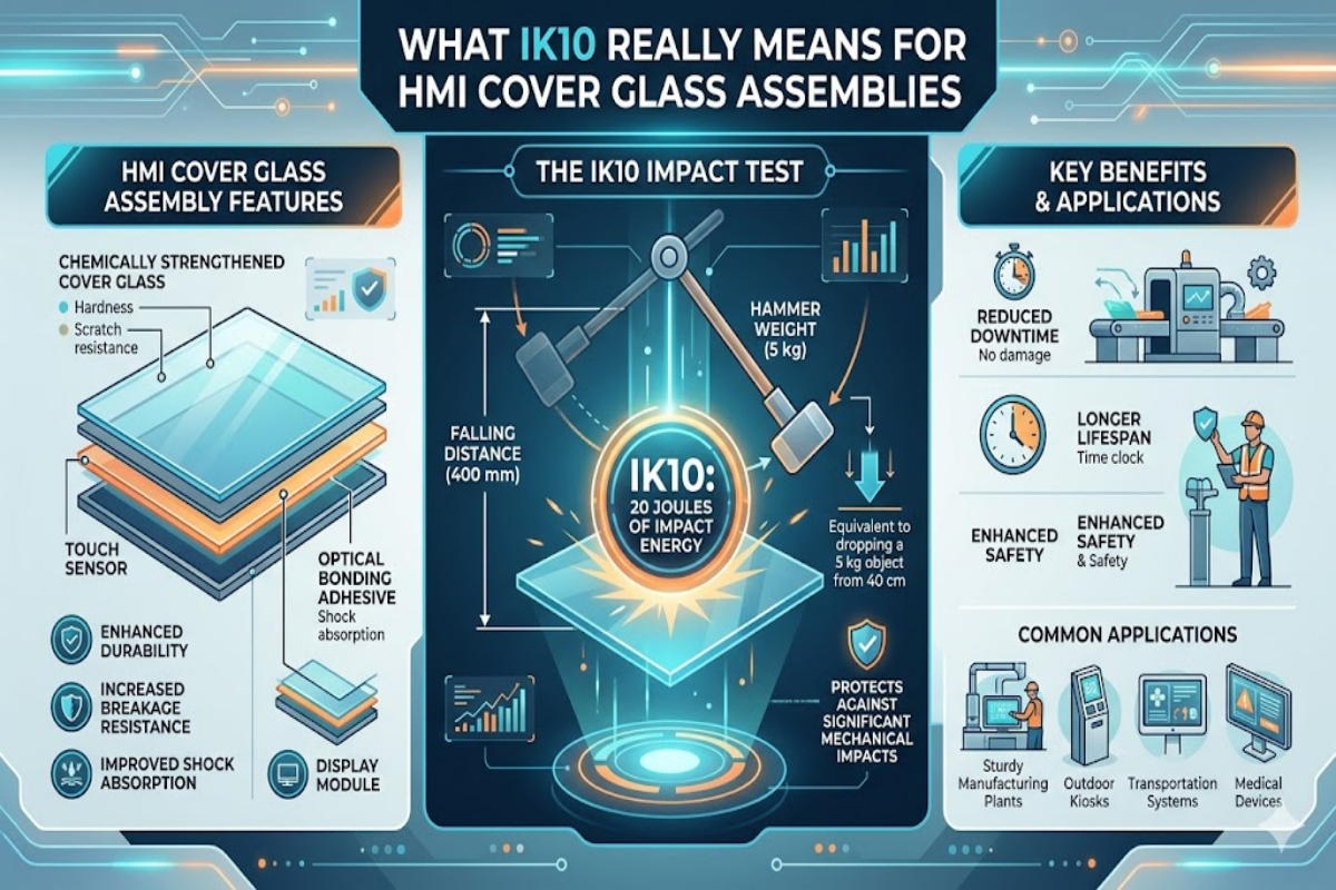
An IK10 rating means your cover glass assembly can endure a single 20-joule impact without shattering, developing a crack, or losing function. The test protocol dictated by IEC 62262 and its companion standard IEC 60068-2-75 requires a 5 kilogram steel mass to be dropped from 400 mm above the test article – or alternatively a calibrated Charpy pendulum hammer which delivers the same energy level to the test sample.
20 J
Impact Energy
5 kg
Steel Mass
400 mm
Drop Height
From a practical perspective, 20 joules equates to swinging a heavy wrench into a display panel at full arm speed, or a screen being struck by a piece of factory debris kicked up by a forklift. Each exposed surface of the specimen is subjected to five separate impacts at different angles – front, sides, corners, and top – to replicate the effects of actual strikes which rarely come from a single, easy to predict source.
At our plant we run IK10 validation tests on cover glass samples before sending production batches to the field. These results reveal hazards that lab-grade material specs alone cannot predict: propagation pathways for edge-chip breakouts, adhesive delamination under repetitive shock, and stress fractures originating in drill holes or cutout corners. A pane of glass that looks “strong” on paper can fail on the first pendulum strike if edge finishing or tempering profile is not optimal.
💡 Key Takeaway
IK10 is not merely glass thickness applicability. IK10 testing assesses the system as a whole – glass, adhesion, mounting, and enclosure – as a cohesive response to external loads. A thick pane of poorly bonded glass in the framework can still fail.
Why Industrial HMI Displays Require IK10-Rated Cover Glass

HMI (Human-Machine Interface) panels are placed in situations where physical shock is commonplace – not a black swan. If an institution chooses anything below IK10 in those circumstances, it is allowing a point of failure that costs far more in remediation than the pane itself.
Here are the main application environments where IK10-rated vandal proof glass is required or highly advisable:
| Environment | Impact Source | Why IK10 |
|---|---|---|
| Factory floor HMI | Tools, parts, forklift debris | Uncontrolled projectiles in heavy manufacturing zones |
| Outdoor kiosks & EV chargers | Vandalism, thrown objects | Unsupervised public access; deliberate damage risk |
| Marine & offshore panels | Equipment shifting in rough seas | Vibration + sudden impacts from unsecured gear |
| Mining & heavy equipment | Rock fall, tool strikes | Continuous exposure to high-energy impacts |
| Transportation displays | Vibration fatigue, passenger abuse | Constant mechanical stress + vandalism window |
⚠️ Common Mistake
Many buying departments specify IK08 (5 joules) in order to trim cost, believing their factory or kiosk environment is “low risk.” In reality, a single dropped hand tool or a chunk of ejected material is enough to go well past 5 joules. That jump from IK08 to IK10 represents a 4-fold increase in durability – but the cost difference between 4 mm and 6 mm tempered cover glass is far less than the life-cycle cost of field repairs, production loss, and safety report uploads.
Total up the project cost of failure: replacement glass, engineer travel, production line shutdown while the panel goes down, and personal injury liability from broken shards. In an outdoor installation, one act of vandalism renders a project uneconomical unless each panel receives IK10 up-front.
Glass Material and Thickness Selection for IK10 Compliance
Achieving IK10 levels of toughness begins with selecting appropriate glass for the application. Two major approaches for stiffening HMI cover glass – physical tempering and chemical strengthening – react very differently when the target is 20 joules impact resistance.
| Property | Physically Tempered Glass | Chemically Strengthened Glass |
|---|---|---|
| Practical thickness for IK10 | 4–8 mm | Generally not suitable alone |
| Thickness range | 3 mm and above (no upper limit) | 0.4–2 mm (e.g., Corning Gorilla series) |
| Strengthening mechanism | Rapid cooling creates surface compression | Ion exchange deepens compression layer |
| Typical CS / DOL | ~100 MPa surface compression | CS >450 MPa, DOL >8 μm |
| Break pattern | Small granular fragments (safety glass) | Larger shards (not classified as safety glass) |
| Best fit for IK10 | Primary choice — 6 mm soda-lime tempered is the standard | Supplementary role — adds scratch resistance on thinner panels |
| Post-processing | No cutting/drilling after tempering | Can be cut after strengthening |
Here are the practical implications of this fact: chemical strengthening provides excellent scratch quality and very high compressive stress (CS > 450 MPa with depth of layer > 8 μm in our production line) – but it suits thin glass only. When IK10-level impact protection is required, the glass must be thick enough to absorb 20 joules, and that generally points to physical tempering at 4 mm minimum, with 6 mm being the more standard dimension for most sizes of HMI panel.
The choice of parent material should not be disregarded. Soda-lime glass is the most affordable tempered IK10 cover glass and suitable in most machinery-based HMI environments. Aluminosilicate offers higher inherent resilience – maintaining IK10 with a thinner profile, at higher material cost. It is better suited to applications where weight or optical performance is critical.
We routinely manufacture IK10 rated cover glass in soda-lime substrates and aluminosilicate substrates. 90% of industrial HMI IK10 applications can use 6 mm Tempered soda-lime glass with proper edge finishing for IK10 performance at the lowest cost.
— SW Glass Engineering Team
💡 Key Takeaway
For any IK10, pick physically tempered glass in 4-8 mm thickness. Use chemical strengthening as an add on for scratch resistance, not as the primary impact protection strategy.
How Cover Glass Assembly Methods Affect IK10 Performance

A cover glass panel that passes IK10 in a test bench can fail in the field depending on the assembly technique. How cover glass is bonded to the display module and placed in the enclosure housing determines if the glass will take the impact, or transfer the load to a weak point resulting in a crack.
There are two primary bonding strategies for HMI cover glass assemblies:
Optical Bonding (OCA/OCR)
Optical bonding uses an OCA film or OCR liquid resin to eliminate the air gap between cover glass and the LCD or touch sensor. OCA/OCR spreads across the entire interface, creating an optical composite where the cover glass and display work as a single, rigid element.
For IK10 use, optical bonding offers a clear mechanical advantage: impact energy is spread across the cover glass rather than concentrated at the edge gasket points. It is much more resistant to the type of impact IK10 testing applies.
Gasket (Air Gap) Bonding
Gasket mounting bonds the cover glass to the housing by a perimeter foam or rubber seal. It is lower cost and easier for field service. However, the air gap causes more deflection on impact, and stress greater at the gasket contact points—and more likely to crack an edge.
💡 Pro Tip — Our Assembly Selection Process for IK10 Projects
For select IK10 applications, we approach the decision of optical bonding versus gasket mounting by taking three steps:
- Display size: Panels larger than 10 inches benefit most from optical bonding because the unsupported glass span increases deflection risk under impact.
- Field repairability: If the customer is expected to replace cover glass repeatedly in the field, gasket mounting with thicker glass (8mm) may be a better compromise than optical bonding.
- Optical quality: Outdoor-readable displays usually require optical bonding for sunlight readability, but that advantage in IK10 durability does not require additional structural support.
No matter how the cover glass is mounted, the structural support from the housing must adequately support the edges of the glass. A free-floating cover glass with only adhesive contact at the bezel will not perform as well as a cover glass mounted within a channel with gasket contact on all four sides of the glass in IK10 impacts.
IK10 and IP Ratings — Complementary Protection for HMI Enclosures

IK and IP ratings protect against different threats and are regulated by different codes. The IP (Ingress Protection) code under IEC 60529 determines protection against dust and water ingression. The IK code (IEC 62262) determines protection against mechanical impacts. Neither code replaces the other – an enclosure with an IP67 rating can still have a cover glass that cracks when struck with a wrench, and a panel rated IK10 can still leak water through unsealed gaskets.
The IPS and IKs are typically specified as a pair for industrial HMI installations. Some of the most frequently encountered IP + IK combinations found in customer specifications are:
| IP + IK Combo | Protection Level | Typical Application |
|---|---|---|
| IP54 + IK08 | Dust-protected, splash-proof, moderate impact | Indoor factory HMI, control room panels |
| IP65 + IK08 | Dust-tight, low-pressure water jets, moderate impact | Washdown-area panels, food processing |
| IP65 + IK10 | Dust-tight, water jets, maximum impact | Outdoor kiosks, EV charging stations |
| IP66 + IK10 | Dust-tight, powerful water jets, maximum impact | Marine displays, heavy industry, mining |
| IP67 + IK10 | Dust-tight, temporary immersion, maximum impact | Submersible equipment, extreme environments |
When you specify cover glass for a dual-rated enclosure, the glass itself primarily contributes to the IK rating. IP protection relies upon the sealing system – gaskets, adhesive beads, and O-rings around the glass perimeter. Optical bonding solves both problems – removes the internal air gap (eliminating a potential pathway for water ingress) and also increases impact rigidity in one step.
💡 Key Takeaway
Always specify IK and IP ratings together. An HMI panel rated IP65 without an IK rating has no guaranteed impact protection – even though it is fully sealed against dust and water.
How to Specify IK10 Cover Glass for Your HMI Project
Submit an RFQ on IK10 cover glass, the intricacy of your specification will directly impact whether your first sample passes testing or you’ve got to go through many revision cycles. Below is the specification checklist our engineering team suggests for any IK10 cover glass application:
- ✔
Glass type and thickness: Specify tempered soda-lime or aluminosilicate, with exact thickness (e.g., 6 mm ± 0.2 mm). State whether chemical strengthening is also required. - ✔
Dimensions and tolerances: Provide L × W in mm with tolerance range. Include corner radius, edge profile (seamed, polished, or pencil), and any chamfer requirements. - ✔
Holes, cutouts, and notches: All CNC features must be completed before tempering. Provide a dimensioned drawing with position tolerances for each feature. - ✔
Surface treatments: Specify AG (anti-glare), AR (anti-reflective), or AF (anti-fingerprint) coatings. State whether the coating is applied before or after tempering, and on which surface(s). - ✔
Silk-screen printing: Define ink color(s), print area dimensions, layer count, and any logo or icon requirements. Bezel printing is common for HMI cover glass to frame the active display area. - ✔
Bonding method: State whether the glass will be optically bonded (OCA/OCR), gasket-mounted, or adhesive-tape bonded. This affects edge tolerance requirements and the minimum bezel width. - ✔
IK and IP target ratings: State both explicitly. If your enclosure design is already finalized, provide the housing drawing so the glass manufacturer can verify that the mounting geometry supports IK10 performance.
Missing any one of these items at the RFQ stage usually adds 1-2 sample revision cycles – each costing 2-3 weeks of lead time on a conventional custom glass job. The more complete your specification, the sooner you get a production-ready cover glass that passes IK10 testing.
💡 Key Takeaway
A complete specification at the RFQ stage is the most important factor in preventing sample failures and schedule delays. Be specific as to glass type, size, surface treatment, bonding method, and target IK/IP ratings.
Frequently Asked Questions

Q: What is the difference between IK10 and IP ratings?
View Answer
IK measures mechanical impact resistance (IEC 62262). IP measures dust and water ingress protection (IEC 60529). Industrial HMI projects specify both – for example, IP66 + IK10.
Q: Can chemically strengthened glass pass IK10 testing?
View Answer
Chemically strengthened glass, by itself, is generally not enough for IK10. Chemical strengthening is most suitable for thin glass (0.4-2 mm), and IK10 demands the type of mass and rigidity that only thicker glass can give – typically 4-8 mm physically tempered panels. On top of tempered glass, chemical strengthening can increase the scratch resistance, but it is no substitute for the thickness needed to survive a 20-joule impact.
Q: What glass thickness is needed for IK10?
View Answer
Between 4 mm and 8 mm of physically tempered glass, depending on panel size and housing assembly design. A 6 mm tempered soda-lime panel with reinforced edges supports most HMI applications in the 7-15 inch range. Consider 8 mm for panels exceeding 15 inches, or free-standing kiosk applications, where the glass span is greater and less strongly supported by the housing frame.
Q: Does IK10 cover glass affect touch screen sensitivity?
View Answer
It is true that thicker glass does add distance from finger to the touch sensor, reducing effective capacitive touch sensitivity. But today’s projected capacitive (PCAP) touch controllers can be finely tuned to operate reliably through 6-8 mm glass. Optical bonding improves the touch response by removing the air gap which would add a second dielectric layer between finger and sensor. Consult your display integrator for touch controller compatibility when ordering IK10 cover glass.
Q: Is IK10 required for outdoor HMI displays?
View Answer
No international standard requires it. But if your touchscreen HMI is outside, also may be left unattended, or in a rigorous heavy-industry environment, IK10 is the sensible minimum. Municipal transit agencies and EV charging networks are increasingly specifying IK10 as a precondition for any countertop/public access station – and insurance agencies may inquire as to why a lower number was ordered if it is damaged in a vandalism claim.
Q: What coatings are compatible with IK10 cover glass?
View Answer
AG ( anti-glare), AR ( anti-reflective), and AF ( anti-fingerprint) coatings are all compatible with IK10-rated tempered cover glass. AG etching occurs before tempering, and AR and AF coatings are normally applied afterwards. These coatings have no impact on impact resistance if properly applied. For landscape touchscreens, an anti-glare + anti-fingerprint is typical – minimizing reflected light and keeping the surface easiest to clear.
Need IK10 Cover Glass for Your HMI Project?
SW Glass can provide tailored IK10-rated cover glass assemblies for industrial displays from prototyping to high volume manufacturing. Please provide your specs and we will draft you a quotation within 48 hours.
About This Guide
This article was written by the engineering team at SW Glass (Dongguan Saiwei Glass Co., Ltd), an OEM cover glass manufacturing specializing in engineering solutions for industrial displays, HMI, and electronic interfaces. We are registered ISO 9001:2015 and EN 12150 manufacturers with CNC processing, chemical strengthening, high performance screen printing, and the surface treatment line manufacturing in excess of 1 million units for various verticals, including factory automation, marine, and life sciences. Our IK10 test data and material suggestions herein are garnered from our actual production metrics – hundreds of requested custom cover glass solutions executed for factory automation, marine, medical, and mass transit systems.
References & Sources
- IEC 62262:2002 — Degrees of Protection Provided by Enclosures Against External Mechanical Impacts (IK Code) — International Electrotechnical Commission
- EN 62262 — IK Rating Standard History and Overview — Wikipedia
- Ingress Protection (IP) Ratings — International Electrotechnical Commission
- IEC 62262:2002/AMD1:2021 — Amendment 1 (Addition of IK11) — International Electrotechnical Commission