Get in Touch with Saiweiglass



PCAP cover glass is the first thing an operator touches – and the last thing most design engineers dwell on. Of all the touch technologies in an industrial environment, few compare to projected capacitive touch systems; and for those systems, the PCAP cover glass is not merely an inert layer. It is directly responsible for signal strength, optical performance, environmental resistance, and whether or not gloved fingers register on screen.
Mis-specify the PCAP cover glass and your industrial touch sensor leaves with ghost touches, dead areas, or a cracked display 6 months after installation. This article defines seven design specifications – covering material choice, dielectric thickness compromises, EMI shielding – that separate a dependable pcap touch screen matrix from a fully-voided warranty.
How Projected Capacitive Touch Technology Works

projected capacitive touch (PCAP) monitors capacitance by observing capacitance anomalies at the point of intersection between a grid of transparent conductors embedded into the cover glass. A PCAP touch sensor pairs two layers of patterned indium tin oxide (ITO) conductors – one providing drive (X-axis) and the other sense (Y-axis) – spaced apart in a dielectric. As a conductive finger or object enters a proximity charge coupled with the Kiri, it induces a reading of capacitance, which the controller system uses to locate the touch point.
On top is the PCAP Angoshel layer, bottom is the ITO electrode pattern, separated by a dielectric – beneath is the glass substrate, until the LCD/TFT of the display above. While each additional layer in a projected capacitive touchscreen build-up adds optical attenuation and impacts touch reception, a limited number of layers minimizes system inefficiency.
Mutual capacitance requires that the charge variation present at each X/Y intersection in the electrode pattern be measured independently, supporting reality-perfect (multi-touch) detection without ghosting. Self-capacitance must measure capacitance separately on each row and column; while it is simpler to implement, ghost coordinates may appear during the simultaneous detection of excessive touch points.
Typical parameters for an ITO film used in a PCAP touch sensor include 10-100 ohms resistivity (teraced at the square), 50-200 nm thickness, and 85% transmittance through the optical. Most standard PCAP patterns employ either a diamond pattern – nine interconnects in a 3×3 grid, interlinked by traces – or a matrix pattern – nine groups of parallel bars connected by traces. Diamond patterns offer flatter electric fields across the sensor.
💡 Key Takeaway
Mutual capacitance supports true multi-touch detection. Self-capacitance – while easier to design and implement – cannot reliably eliminate ghost coordinates in the simultaneous registration of two touch points on the same trace.
For a discussion on the electrostatic principles behind this technology, see this overview of capacitive sensing. Analog Devices also published a detailed breakdown of projected capacitive systems from the controller perspective.
Cover Glass Material Selection for PCAP Touch Screens
Material choice has a cascading effect from impact resistance to optical transmittance to how much capacitance reaches the touch sensor below. touch screen use three glass families, each with its own set of pros and cons.
| Property | Soda-Lime | Borosilicate | Aluminosilicate |
|---|---|---|---|
| Hardness (Mohs) | 6–7 | 7 | 7–8 |
| Strengthening | Chemical or thermal | Thermal | Chemical (ion exchange) |
| Max Compressive Stress | ~300 MPa | ~200 MPa | >700 MPa |
| Thermal Shock Resistance | Low | High | Medium |
| Cost | $ | $$ | $$$ |
| Best For | Indoor kiosks, standard HMI | High-temp environments | Heavy-duty industrial, outdoor |
Chemically strengthening by ion exchange is recommended for all cover glass under 3 mm in thickness. During ion exchange, glass is placed in a bath of molten potassium nitrate at about 400C. The replacement of small sodium ions with larger potassium ions induces a layer of compressive stress in the surface of the glass. Aluminosilicate compositions will produce a layer of DOL greater than 40 m and a compressive stress above 700 MPa in soda-lime glasses.
⚠️ Common Mistake
Indicating thermal temper for all cover glass under 3 mm in thickness. To induce sufficient temperature differential between surface and core to induce desirable compressive stress – about 3 mm wide glass thickness is required. All thinner panes are free of significant stress. Chemically strengthening is your only option.
For indoor standard HMI applications, soda-lime and chemically strengthened glasses provide the best performance at optimal cost. Industrial strength; baked-in impact, abrasion, even thermal variation; aluminosilicate glass is your best bet. Borosilicate; applications facing rapid and extreme temperature variation – oven controls, outdoor HMI in frozen climates.
When specifying industrial HMI cover glass always include the effective strengthening method with DOL test documentation from your supplier. Always specify edge profiling, hole drilling and customization of reinforced glass before tempering; chemical temper cannot be cut or drilled.
Cover Glass Thickness and Touch Sensitivity Trade-offs

cover glass thickness is perhaps the most critical physical component of a pcap touch screen. A misstep results in a shattered HMI assembly. Each additional millimeter of glass increases the amount of electric field coupling required between your finger and the ITO sensor – directly reducing signal-to-noise ratio at the controller.
| Thickness | Touch Type | Signal Level | Max Touch Points | Typical Application |
|---|---|---|---|---|
| 0.7–1.1 mm | Mutual cap | High | 40 | Consumer tablets, thin HMI |
| 1.5–2.0 mm | Mutual cap | Medium | 20 | Standard industrial HMI |
| 3.0–4.0 mm | Mutual/Self cap | Low | 10 | Rugged HMI, outdoor |
| 6.0–8.0 mm | Self cap preferred | Very low | 5 | Vandal-proof kiosks |
| 10–12 mm | Self cap only | Minimal | 2 | Extreme protection |
≤ 2.0 mm
Reliable mutual-cap limit
40 pts
Max touch points (thin glass)
12 mm
Maximum viable thickness
Mutual capacitance reliably penetrates the entire thickness of cover glass up to 2.0 mm thick. Once that is exceeded, controller firmware tuning on signal response becomes mandatory – and at 4 mm thick or greater, many designs switch to self-capacitance or hybrid sensing modes. Signal strength decays roughly as the square of the distance between finger and electrode, so doubling the glass thickness cuts signal to approximately one quarter.
⚠️ Common Mistake
Using thick cover glass to survive touch panel impacts yields substandard control performance without budget for controller tuning and firmware adjustments. A 4 mm falloff property pane with a default-configured controller will never leave the assembly in one piece without touch failure.
Compare how cover glass specifications affect HMI touch performance across myriad PCAP touchscreen applications and display sizes.
Surface Treatments — Anti-Glare, Anti-Reflective, and Anti-Fingerprint Coatings

Surface coatings determine whether operators can actually read the display of your HMI in the real world-in all its sun-facing glory, that long fluorescent tubes reflected off the factory floor, or hands smearing lube across the control glass. One well-selected coating turns a washed-out screen into a readable one.
| Coating | Function | Key Spec | Best For |
|---|---|---|---|
| AG (Anti-Glare) | Scatters reflected light | 5–25% haze (tunable) | Bright factory floors, outdoor HMI |
| AR (Anti-Reflective) | Reduces surface reflection | Reflection <0.5% at 550 nm | Medical displays, precision readability |
| AF (Anti-Fingerprint) | Oleophobic layer repels oils | Contact angle >110° | High-traffic retail, food processing |
| AG+AR Combo | Dual coating | Low haze + low reflection | Outdoor sunlight-readable HMI |
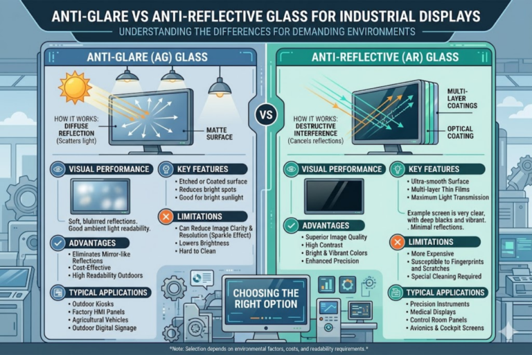
For factory-floor HMI where operators wear gloves, AG coating with 8-15% haze is the proven choice. It diffuses overhead light sources while having negligible impact on resolution at normal viewing distance. For clean-room or medical HMI where pixel-level clarity matters, AR coating with <1% reflection outperforms AG because it preserves native display resolution.
AG and AR are “like day and night” in that AG lightly scatters an incoming light beam in a multitude of directions while AR employs multi-layer optical interference devices – thin dielectric layers versus grazing micro-texture, respectively. The key difference is the intent: scatter reflections, or completely eliminate them.
💡 Pro Tip
For outdoor PCAP touchscreen applications, combine AR coating (reflection <1.5%) with low-haze AG (5-8%) for the best readability without sacrificing image sharpness. According to Anders Electronics, this dual-coat approach is well established for sunlight-readable HMI panels.
AF coatings are best applied as a top layer on top of AG or AR. They use fluoropolymer-based oleophobic chemistry to reduce surface energy and cause water and oils to bead up instead of spreading thin. Select a specification that has a water contact angle (WCA) > 1100 for at least 500,000 touch cycles to maximize durability and minimize surface contamination.
Optical Bonding vs Air Gap for Industrial PCAP Displays

The method by which the cover glass adheres to the LCD directly affects sunlight readability, touch registration, and long-term reliability. Make your choice between an optical bonding approach (filling the air gap with adhesives such as OCA or OCR) or an air-gap assembly method (the entire cover glass sits held above the display on perimeter tape in an air cavity).
| Factor | Optical Bonding (OCA/OCR) | Air Gap (Perimeter Tape) |
|---|---|---|
| Contrast Loss | <5% | 5–20% |
| Sunlight Readability | Excellent | Poor |
| Impact Resistance | 3–5× higher | Baseline |
| Parallax | Eliminated | Noticeable at angles |
| Condensation Risk | None | Yes — moisture ingress over time |
| Rework / Repair | Difficult | Easy |
| Cost Premium | +$3–$15/unit depending on size | Baseline |
Based on our experience providing factory-integrated cover glass assemblies to industrial customers, air-gap bonded PCAP displays in humid factory environments develop internal fogging after 12-18 months. Humidity slips past perimeter tape seams and fogs up the inner surface, collapsing viewability and touch registration. Bond the cover glass with OCA or OCR instead to eliminate that failure mode altogether; fill the cavity with adhesive instead of air.
“Optical bonding increases manufacturing complexity and cost, but eliminates a long-term failure point. For any PCAP display deployed outside controlled environments — warehouses, outdoor installations, food processing — we consider it mandatory.”
— Saiwei Glass Engineering Team
OCA (coated-aggressive adhesive) works well for relatively small formats up to 15″ or so, but it’s best to opt for OCR (coated-aggressive resin) for larger-format or irregular-sized displays for customized. It is dispensed as a liquid and cured with UV light in place for a perfect match of refractive index with the glass and display. This significantly reduces internal reflections at the interface.
⚠️ Important
optical bonding makes a custom display nearly impossible to repair in the field. When an LCD or TFT panel is failing, you can’t usually separate a bonded cover glass assembly without damage to either the LCD or the cover glass.
On the bonding side, UICO’s touchscreen bonding guide offers mechanical parameters comparisons and considerations. Interelectronix published a technical note on optical bonding for pcap touch screens with lamination process flow and parameters.
Controller Tuning for Glove Mode and Thick Cover Glass

cover glass addresses the mechanical factors, but your pcap touch controller firmware is what determines if your HMI responds at all in real world conditions – with gloved operators, thick protection glass, and noise from electrical switching elsewhere in the plant.
The four most relevant parameters of controller are signal threshold (how much capacitance must change to create registered event), gain (raw sensor signal is amplified by a specified amount), noise filtering (algorithms that discriminate between real touches and other environmental effects), and water rejection (intelligent logic that reasons out potential water transcription from a finger just contacting the glass).
Glove mode simply raises the controller threshold high enough for the small capacitance delta caused by a gloved finger contact against 1.1 mm glass. With bare fingers, the value might be 50 counts. With a thin nitrile glove, 20 counts. Thick leather glove gloves worn in welding shops or heavy manufacturing might only be 5 or 8 counts. Different glove types require different threshold adjustments, and a PCAP touch sensor is fine-tuned for these sensitivities after installation.
Thick glass amplifies these effects. PenMount or UICO PenMount solutions are capable of sensing up to 10 mm, but only if the gain, noise filtering, and threshold are tuned specifically for the application. A 3 mm glass application that detects a bare finger may not function properly with a 6 mm glass and leather glove unless firmware adjustments are carried out for that exact situation.
- Firmware Tuning Checklist
- ✔
Define cover glass thickness and material before ordering controllers - ✔
Specify every glove used in the application (material, thickness) - ✔
Request a firmware tuning report from the controller vendor - ✔
Water droplet tests on the glass surface (water rejection validation) - ✔
Validate false-touch immunity in the actual operating environment - ✔
Confirm multi-touch accuracy with the specified glass and bezel configuration
⚠️ Common Mistake
Implementing production solutions with shipped default PCAP firmware. Default configurations assume bare fingers operating through 1.1 mm glass. An HMI shipped with such defaults and a 3 mm cover glass will encounter customer complaints within weeks of deployment – inconsistent touch dead zones, input misses, and phantom inputs near the bezel bounds.
Analog Devices gives a detailed overview of projected capacitive touch systems, PCAP architecture, and the operating system communications protocol layer.
EMI Shielding and Grounding in PCAP Cover Glass Assemblies
PCAP touch sensors are extremely susceptible to EMI coupling. The ITO electrode grid filaments are an antenna, and industrial plants generate broadband noise at all frequencies from all directions – varying frequency drives (VFDs), servo motors, switching power supplies, and high-current bus bars all create broadband EMI that couples into the touch sensor.
The result is well-understood: ghost touches that trigger errant instructions, delayed action where operators hammer the screen with repeated contact, and total HMI distemper during motor startup. A touch screen panel (NEMA 4X subpanels, ruggedized display glass) placed within 30 cm of a 10 HP VFD with no EMI mitigation measures in place will start misbehaving in seconds after the motor starts running at VMF.
IEC 61000-6-2 industrial immunity standard is a full set of ED examinations corresponding to an industrial environment. All pcap touch screen systems destined for manufacturing locations should be subjected to similar testing. IEC 61000-6-2 industrial immunity standard specifies the conducted and radiated interference levels that a piece of equipment can sustain without malfunctioning.
- Grounding Best Practices
- ✔
Bond the ITO shield layer to chassis ground using the conductive gasket - ✔
Keep the ground path length under 20 mm – shorter paths are less inductive - ✔
Use TVS diodes at each I/O connector on the controller board that is exposed to a high radiosity field - ✔
Shield FPC/FFC cable routing away from high-current conductors - ✔
Physically isolate the touch controller power supply from the motor driver circuitry.
⚠️ Common Mistake
Blocking ground prevents static charge from migrating to the cover glass surface. This risk of built-up negative charge produces a DC offset on the sensor electrodes that the controller tries to interpret as a tangible touch which leads to the problem of ghost touches and false response delay. In winter conditions or when conductive material is nearby the issue worsens and is frequently impossible to remediate without repositioning the equipment. Always check ground continuity during your temperature range testing.
A conductive ITO border ring around the active touch area, connected to chassis ground through the shortest possible path via conductive gasket, is the single most effective measure against EMI-induced touch errors. This ring acts as a Faraday shield that intercepts radiated noise before it reaches the sensing electrodes.
Frequently Asked Questions

Q: What does PCAP stand for on a touch screen?
View Answer
PCAP stands for Projected Capacitive — a touch technology that uses transparent ITO electrodes beneath the cover glass to detect finger contact through changes in capacitance.
Q: What is the difference between PCAP and resistive touch screen?
View Answer
PCAP uses electrostatic charge detection through a glass surface, supporting multi-touch and glove operation with no moving parts. Resistive touch screens rely on two flexible conductive layers that make physical contact under pressure, limiting them to single-touch input and shorter operational life. PCAP delivers better optical clarity (>90% transmittance vs approximately 80% for resistive), higher durability since there are no wear-prone flex layers, and more accurate touch registration across the full display area. Resistive screens cost less per unit but require replacement more frequently in high-use industrial environments.
Q: Does PCAP work with gloves?
View Answer
Yes. Industrial PCAP controllers detect gloved touches when firmware is tuned for glove mode, handling leather work gloves up to 5 mm thick.
Q: What types of cover glasses are used in PCAP touch screens?
View Answer
Three glass families dominate PCAP cover glass applications. Soda-lime glass is cost-effective with good chemical stability, making it the standard for indoor HMI panels and digital signage. Borosilicate glass handles temperature extremes better due to its low thermal expansion coefficient — suitable for environments with rapid temperature swings. Aluminosilicate glass (including branded versions like Gorilla Glass) delivers the highest impact resistance, with compressive stress exceeding 700 MPa after chemical strengthening, making it the go-to material for rugged industrial HMI, outdoor kiosks, and military-grade displays. Cover glass thickness ranges from 0.7 mm for consumer-grade panels up to 12 mm for vandal-proof installations.
Q: What is optical bonding for PCAP displays?
View Answer
Optical bonding fills the air gap between cover glass and LCD with optically clear adhesive (OCA) or resin (OCR), cutting contrast loss from over 20% to under 5% while boosting impact resistance 3–5 times. It costs more and complicates field repairs.
Q: How thick can PCAP cover glass be?
View Answer
PCAP cover glass reaches 12 mm in extreme vandal-proof applications, though thicker glass drastically reduces touch signal strength. Mutual capacitance works reliably up to about 2 mm without controller modifications. Between 2 mm and 6 mm, custom firmware tuning is required to maintain accurate touch detection. Above 6 mm, self-capacitance mode or hybrid sensing becomes necessary because mutual-cap signal drops to roughly one-quarter of its baseline at double the standard glass thickness. Most industrial HMI projects land between 1.5 mm and 4 mm as the practical sweet spot — enough mechanical protection to survive factory environments without requiring exotic controller configurations.
Need Custom PCAP Cover Glass for Your Industrial HMI Project?
Saiwei Glass, offers custom cover glass solutions with AG, AR, AF coatings, chemical strengthening to 700+ MPa compressive stress, and optical bonding services – all optimized for your pcap touch screen application.
About This Technical Guide
The following performance specifications were designed for industrial PCAP touchscreen applications by Saiwei Glass, a leading manufacturer of cover glasss with a focus on chemical strengthening, full glass fabrication, and surface modifications such as AG, AR, and AF coatings. The recommended controller tuning and analysis methodology described in this paper results from actual integration work with industrial OEM partners in factory automation, medical device, and outdoor kiosk projects. Our engineering team carefully compares each cover glass specification with the target environment.
References & Sources
- Capacitive Sensing — Wikipedia
- Projected-Capacitive Touch Systems from the Controller Point of View — Analog Devices
- IEC 61000-6-2 Industrial EMC Immunity Standard — IEC
- Anti-Glare vs Anti-Reflective: What Is the Difference? — Anders Electronics
- Touchscreen Bonding Options — UICO
- Optical Bonding for PCAP Touch Screens — Interelectronix