Get in Touch with Saiweiglass


How to Choose the Right Touch Display Module for Your Application
Choosing a touch display module requires balancing the needs of display clarity, touch response, interface bandwidth and environmental durability against project schedule and budget. This article guide us through the engineering specifications that matter most, with actual specs and utilized selection algorithms for industrial, medical or other embedded touchscreen projects.
Quick Specs
| Display Types | TFT LCD, IPS, OLED |
| Size Range | 0.96″–15.6″ |
| Touch Technologies | Capacitive (PCAP), Resistive |
| Interfaces | SPI, I2C, RGB, LVDS, MIPI DSI, HDMI |
| Operating Temperature | -20°C to +70°C (standard) |
What Is a Touch Display Module?

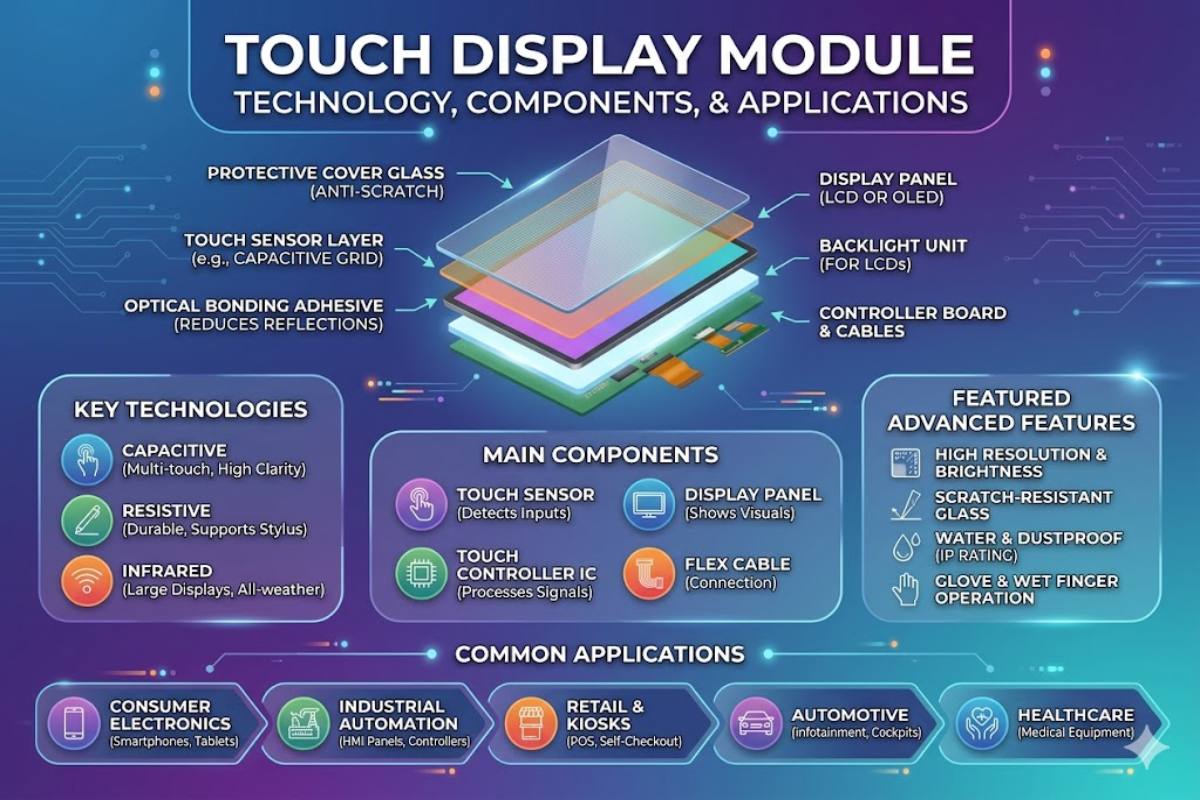
The touch display module is a pre-assembled unit that contains a TFT or OLED display, a touch input layer, driver electronics, and a housing fixture for direct integration into an industrial computer or appliance. Modules communicate digitally (SPI, I2C, HDMI, or LVDS) presenting visual output and touch position data.
A typical touch display module displays covers glass, touch sensor, optically bonded adhesive, display, backlight, and electronics stacked in the following configuration, from front to back:
- Cover glass (0.7-3.0mm) – mechanically tough, chemical strengthened for scratch and impact resistance
- Capacitive (ITO on glass) or resistive (ITO on PET film) touch sensor layer
- Optical bonding adhesive or air gap – bonds the touch sensor to display, optical bonding minimizes internal reflection
- OLED or TFT display panel – determines resolution, contrast, color fidelity, view angle and power draw
- LED backlight (not included in OLED models)
- Electrical driver board / flex cable assembly -applies pixel-by-pixel voltage to create raster image
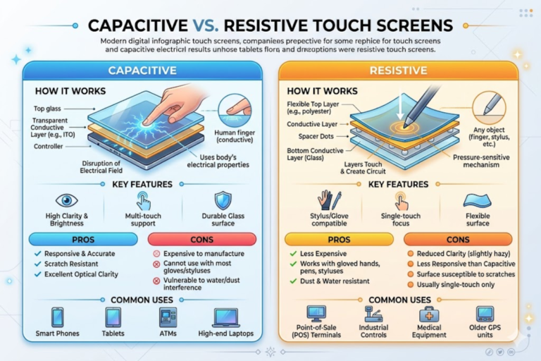
Capacitive touch input has exceeded resistive as the dominant touch technology on all common display sizes by 2025, according to the industrial market researcher MarketsandMarkets. Consumer multi-touch devices (smartphones, tablets, game consoles) have pushed projected capacitive (PCAP) panels toward higher transmittance and longer protective life — each a defining feature the industrial touch screen community now expects. However, single touch resistive panels are still the right choice for productivity applications requiring gloved or stylus control. See below for the technical reasons:
Capacitive vs Resistive Touch Screen Modules
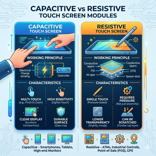
Choosing between capacitive and resistive touch affects size, cost, interface bandwidth, and user experience. Capacitive responds to any input whether a finger, glove, stylus or stylus across most operating conditions; resistive requires a gloved finger or pen input but remains effective in moist or dirty environments. Here are the spec differences:
| Specification | Capacitive (PCAP) | Resistive |
|---|---|---|
| Optical Transmittance | ~90% | 78–82% |
| Touch Points | Up to 10 (multi-touch) | 1 (single touch) |
| Activation Method | No pressure needed | Physical pressure required |
| Lifespan | 50M+ touches | 1M–35M touches |
| Glove Operation | Requires capacitive-compatible gloves or firmware tuning | Works with any gloves |
| Scan Frequency | 100 Hz+ | N/A (analog pressure) |
| Surface Hardness | 7H tempered glass | Flexible polyester film |
| Operating Temp | -20°C to +70°C | -20°C to +70°C |
Capacitive Touch Advantages
- Multi-touch gesture support (pinch, zoom, swipe)
- Better visual clarity through 90% light transmittance
- 50M+ touch lifespan reduces field replacement costs
- Hardened glass surface resists scratches and chemical exposure
Capacitive Touch Limitations
- Cannot be activated by rubber gloves greater than 10mm thick
- Typically costs $8–$15 more than resistive at a 7-inch screen size
- Can be triggered by surface water droplets without software filtering
Resistive Touch Advantages
- Can be used with any input device—bare finger, gloved hand, stylus, or pen
- More cost effective per module especially at small sizes (<5in)
- Can be falsely triggered by water or surface dirt
Resistive Touch Limitations
- Single-touch only — no multi-touch gesture support
- Polyester film surface scratches more easily than glass
- Lower transmittance (78–82%) reduces display clarity under bright lighting
⚠️ Common Mistake: Specifying resistive touch for a user interface that requires pinch-to-zoom or multi-finger gestures. Resistive technology supports single-point input only. If your UI design includes multi-touch interaction, capacitive PCAP is the only viable option among standard touch screen modules.
TFT LCD Display Module Technologies and Panel Types
Display illuminator sets the performance template for each product. Brightness, power draw, color calibration, and view angle are all a function of the LCD TFT technology chosen. Two dominant panel types compete in the embedded TFT market:
| Specification | TN Panel | IPS Panel |
|---|---|---|
| Viewing Angle | 45°–55° | 178° (all directions) |
| Brightness | 500–700 nits | 1,000–5,000 nits |
| Contrast Ratio | 600:1–1,000:1 | 1,000:1–1,500:1 |
| Color Uniformity | ~70% | ~95% |
TN (twisted nematic) – inexpensive, tolerates contact bright illumination, but suffers from limited view angle, muted colors and high power consumption
If you are designing a fixed-position LCD display where the user always faces the operator-head-on (at a computer or at an appliance front panel), TN offers 20-30% savings over IPS (In-Plane Switching):
OLED panels provide a very high contrast ratio (per-pixel dimming, blacker than black) over 100,000:1, but are still less prevalent in industrial touchscreen TFT modules due to cost premium, burn-in concern under static-image display conditions, and narrower operating temperature window.
📐 Engineering Note — Sunlight Readability: For outdoor or high-ambient-light environments, a readable display requires three elements working together: optical bonding (eliminates internal air-gap reflections, boosting contrast by 400%), a high-brightness backlight rated at 1,000 nits minimum, and an anti-reflective or anti-glare coating on the cover glass. A TFT LCD rated at 700 nits without optical bonding will appear washed out under direct sunlight even with the backlight at full power.
Always verify your tft lcd display module brightness figure is reflective of actual display position (on the panel surface after bonding) rather than backlight luminance, which can often be 15-20% brighter than what you will see through the glass and touch sensor stack.
Interface Options — SPI, I2C, HDMI, RGB, and LVDS

The connector interface from your controller board to the touch display module drives max resolution, max refresh rate, maximum wiring complexity and maximum cable length – pick the wrong interface and no amount of software optimization or touch motion smoothing will improve display performance.
| Interface | Data Rate | Pins | Max Resolution | Best For |
|---|---|---|---|---|
| SPI | 10–80 MHz | 4 | 480×320 | Small displays ≤3.5″ |
| I2C | 400 kHz–3.4 MHz | 2 | 128×64 | Touch data, small OLEDs |
| RGB/TTL | Up to 50 MHz | 24+ | 1024×600 | Mid-size embedded |
| LVDS | 945 Mbps | 4–8 diff. pairs | 1920×1200 | Industrial, long cable |
| MIPI DSI | 1–2.5 Gbps/lane | 4 lanes | 4K | Mobile, high-res |
| HDMI | 18 Gbps (2.0) | 1 cable | 4K@60Hz | Dev kits, consumer |
Embedded screens based around microcontrollers (STM32, ESP32, NXP i.MX) almost always start at the SPI interface. Four-wire SPI pushes a 2.4”-3.5″ screen nice and fast. But above 5″ / 800480 resolution the limitations of the SPI link, even at 50 Mhz, means you need a parallel RGB interface or LVDS. Refer to your module supplier for system design guidance on matching display and touch interfaces to specific module configurations.
Most display driver boards send commands and get backlight values over the SPI or RGB interface, while the touch controller Board resides on a separate UART or I2C line to provide touch coordinates to the host processor. Capacitive touch controllers almost universally report data over an I2C interface at address 0x38 or 0x5D at 400 Khz, transmitting X / Y coordinate packets at the scan frequency. So even HDMI-connected display modules almost certainly need an I2C channel in the hardware design.
📐 Engineering Note — Signal Integrity: LVDS uses differential signaling pairs, making it highly resistant to electromagnetic interference (EMI). For industrial installations where the controller board sits 1–5 meters from the display module, LVDS maintains signal integrity where single-ended RGB/TTL connections would suffer visible noise artifacts. The NIST electromagnetic compatibility standards provide guidance on testing protocols for industrial display hardware in high-EMI environments.
Touch Display Modules for Industrial, Medical, and Embedded Applications

Core hardware technologies specified in a design requirement vary wildly from environment to environment. A touchscreen display module specified in the lab will have no hope of passing 6 months in a robot factory (or subsequently winning regulatory approval for a medical device).
| Requirement | Industrial | Medical | Embedded / IoT |
|---|---|---|---|
| IP Rating | IP65–IP67 | IP65+ (OR-grade) | IP40–IP54 |
| Certifications | IEC 62368-1, UL | IEC 60601-1, FDA 510(k), ISO 13485 | FCC, CE |
| Temp Range | -20°C to +70°C | +10°C to +40°C | -10°C to +60°C |
| Touch Type | PCAP or Resistive (gloves) | PCAP (multi-touch) | PCAP |
| Special Needs | Vandal-proof glass, sunlight readable | Antibacterial coating, EMC compliance | Low power, small form factor |
Industrial automation and instrumentation modules call for ruggedized displays, inside enclosures exposed to thermal cycling, vibration, impact and spill damage. Use 2.0-3.0mm thick chemically-strengthened cover glass with industrial-grade multi-50,000 cumek /7.5 year lifespan hardware. Full sunlight visibility (1,000+ nits brightness backlights) is a requirement of outdoor-commissioned industrial touch display hardware.
Medical device touch screen hardware faces an additional set of rules. IEC 60601-1 electrical safety regulations need to be satisfied so contact and failure modes are isolated from patient areas, while the touch display module is integrated into a finished product. Use anti-bacterial coatings over toughened, chemically strengthened screen glass for hospital-grade cleaning.
IoT and other small embedded or smart products need small size, low power.3.5″-5″ modules running at 3.3V and taking 150-300mA rounds will be digestible in a battery powered product assembly, or ideal for solar-powered installs. Custom module bezel form factors enable flush mounting into product casework structures.
💡 Pro Tip: An IP67 rating guarantees protection against temporary submersion — 30 minutes at 1 meter depth per IEC 60529. However, verify this with actual submersion testing on your assembled unit, not just splash tests on the module alone. Gasket compression, cable entry points, and mounting hardware all affect the final IP rating of the installed system.
How to Select the Right Touchscreen Display Module

Walking through each of the eight engineering choices in order, each one pulls the specification target narrower and narrower. Cut large steps, skip a node in the mosaic, and you end up with mismatched components or an oversized, overspecced (and overpriced) solution.
- Determine operating environment: indoor, outdoor, demanding (water/dust ingress) or clean room.
- Identify touch mechanism: capacitive for multi-touch, 5 or 10 finger gesture interaction, resistive for gloved glove or stylus use.
- Select panel technology: IPS for wide angles, TN if maximum budget for fixed position.
- Match interface to controller bandwidth – SPI for small screens, LVDS for industrial distances
- Indicate the optional cover glass thickness – 0.7mm standard, 1.8-3.0mm for impact area when working in the rugged environment.
- Sjekk om sertifisering krav – IEC 60601 for medisinsk, IP65+ for industriell
- ✔ Consider optical bonding for outdoor or bright-environment deployments
- Request samples and verify touch operation by using them in actual testing prior to mass production.
⚠️ Common Pitfall — Over-Specifying: Paying for IP67 when your product operates indoors and only needs IP54 adds $5–$12 per unit at volume. Similarly, specifying a 1,500-nit sunlight-readable backlight for an indoor-only touch screen module wastes power budget and cost. Match the specification to the actual deployment condition, not the worst-case scenario you might never encounter.
About This Selection Guide
SaiWeiGlass produces chemical reinforced cover glasses and supplies optical bonding services for touch module displays assemblies. Every selection criterion in this guide reflects specifications we apply to protected glass layers on a day-to-day basis – thickness tolerance, surface hardness test, anti-reflective coating application for modules deliver to industrial and medical OEMs. It is about the entire module selection, not only the glass parts.
Frequently Asked Questions
How does a touch display module work?
View Answer
A touch display module consists of placing a touch sensor layer over an LCD or an OLED display panel. When a finger or stylus touches the surface, the display controller detects the location of the input on the touch screen, either by sensing the change in a capacitance (capacitive) or the application of pressure through two conductive layers (resistive), and then relays the location to the host I2C or SPI controller for processing, meanwhile the display driver flat-prints the output onto the screen. The assembly is also encapsulated and attached as one-assemblage along with a single FPC or connector bundle.
What is the difference between capacitive and resistive touch screen modules?
View Answer
Capacitive modules sense the electrical characteristics of the finger, allowing multi-touch input up to 10 separate finger contacts, while resistive modules require physical pressure against the module, and support only single-point one-point input. See the full spec differences table in the capacitive vs resistive section above.
Which touch display module size is best for embedded applications?
View Answer
Typically for most embedded and the IoT applications, the 3.5~7 inch display modules get the optimal compromise between the screen utilization and the power dissipation. A 3.5 inch SPI driven approach is suitable for status dashboards and limited controls. For the more sophisticated GUs, the 7 inch RGB or LVDS module with multi-touch is competitive.
The size should consider the minimum touch target (proposed 9mm 9mm per ISO 9241-420) x number of the items on the screen.
Can touch display modules work with gloves?
View Answer
Any type of glove can be used on the resistive touch modules as they sense pressure; capacitive modules are more sensitive than standard work gloves when used in conjunction with capacitive-compatible gloves or need firmware-based sensitivity tuning.
What interface should I use for my touch screen module?
View Answer
The correct interface is going to depend upon your resolution, the length of your cable (less than 1 meter with a soloed backplane, machine-size displays as long as 3 meters with multiple displays in an array), and the hardware of the controller. For small displays up to 3.5 inches at 480320 resolution SPI is the easiest, fastest, and cheapest way to go with only four conduits. Mid-size modules (between 5-10 inch, 800480 or 1024600) will usually require an RGB parallel or LVDS interface.
For industrial applications where the display board is going to be located a meter or more from the processor several benefits of LVDS for panel-to-panel communications over the board make it the best choice for signal integrity because it uses differential communication. HDMI is fine for development and prototyping but adds expensive and connector bulk to a finished embedded product.
How long do touchscreen display modules last?
View Answer
Capacitive touch sensors carry a rated life cycle of 50 million or more touches. LCD backlights tend to last 30,000 to 50,000 hours at 50% brightness. Resistive sensor lifespan varies more widely — from 1 million touches to 35 million touches depending on film grade and operating force.
Most modules reach end-of-life when the backlight degrades to 50% of initial luminance, not due to the touch sensor.
References & Sources
- Intertek – IEC 60601-1 Medical Device Electrical Safety
- Defining the IEC – IP Rating (IEC 60529)
- NIST – Guide to Standard Test Methods for Industrial Systems
- ISO 9241-420 – Ergonomics of Human System Interaction
- Guide de compatibilitate pe interfață lumină-cursator pentru Riverdi – LCD Díplay
- Newhaven Display – Capacitive and resistive displays.
- MarketsandMarkets: Touch Screen Display Market Report
Related Articles
- Touch Display Modules—Complete catalog of products with various sizes and interfaces
- Capacitive Touch Display Module Solutions Stable Industrial PCAP: module design for industrial PCAP: module design for industrial
- SaiWeiGlass Touch Screen Module Products-View all sizes & specifications of modules available.
- TFT LCD Touchscreen Modules -Touch screens based on TFT modules.
- Custom Touch Display Module Design Services — Tailored module solutions for OEM projects