Get in Touch with Saiweiglass



By Jasonxue | Reviewed by the Dongguan Saiwei Glass Co., Ltd. technical team | Updated November 2026
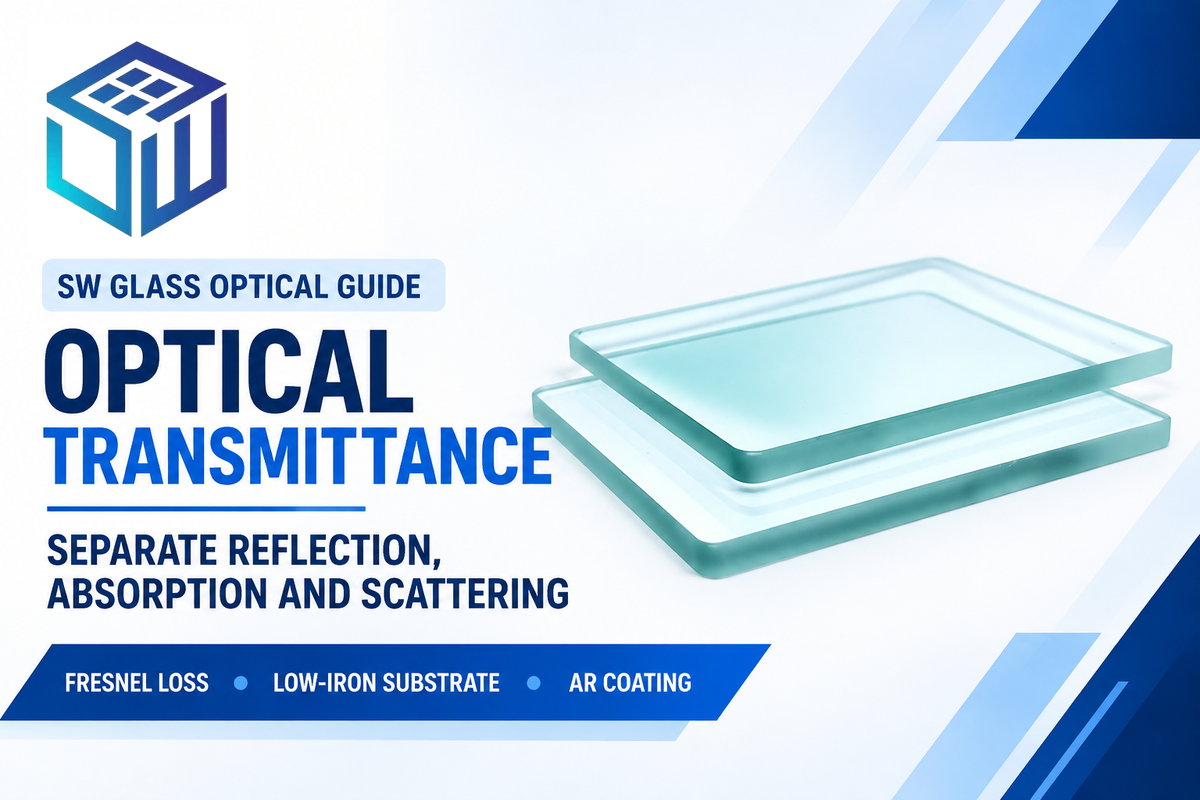
Transmittance is the dimensionless ratio of transmitted radiant flux to incident radiant flux across an optical sample. Engineers write it as T = I / I0, or as percent transmittance %T = (I / I0) × 100. At 0° normal incidence, air-glass Fresnel reflections cap uncoated soda-lime or crown glass (n ≈ 1.52) near 91.7% visible light transmittance. Multi-layer anti-reflective coatings raise light transmission above 98%.
That distinction governs every optical cover glass drawing and purchase order. Chemistry textbooks often treat cell-wall reflection as zero because a solvent reference blank cancels cuvette reflections. However, solid cover glass has no liquid blank; therefore, interface reflection, bulk iron absorption, and surface haze all combine inside one measured percentage.
What Is Transmittance in Optics and Spectrophotometry?
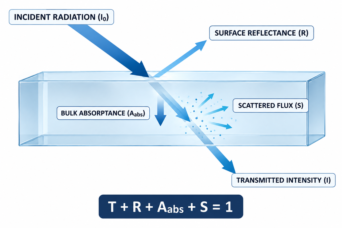
In spectrophotometry, the physical meaning of transmittance is the fraction of incident electromagnetic radiation that exits the opposite side of an optical sample. Specifically, transmittance is the ratio of transmitted light intensity (I) to incident radiation (I0) at a stated wavelength of light (Harper College Spectrophotometry Lab).
Multiplying this decimal fraction by 100 gives percent transmittance (%T), measuring the light that passes through the sample on a 0% to 100% scale. Across the electromagnetic spectrum, energy conservation governs all radiant energy striking a transparent material. Photons that don’t pass through a material are absorbed or reflected, or scattered.
T + R + Aabs + S = 1
Here, T is a fractional transmittance, R is surface reflectance, Aabs is a linear bulk absorptance, and S is scattered flux. Micro-roughness or etched textures cause scattering that separates narrow-angle directional readings from hemispherical total flux, even when bulk heat absorption is zero.
Procurement teams also encounter terminology overlap on architectural glazing prints. In optics, transmittance refers to the dimensionless ratio of transmitted to incident radiant flux across ultraviolet, visible light, and near-infrared bands (ISO 9050:2026). Thermal transmittance (U-factor) instead measures heat transfer rate in W/(m^2·K) under ANSI/NFRC 100-2026. Residential ENERGY STAR Most Efficient windows use triple glazing to hold U ≤ 0.20 Btu/(h·ft²·°F). Mixing optical %T with U-factors stalls quotation reviews.
A single unconditioned percentage on an OEM print is rarely enforceable. The transmittance of a material shifts with thickness, incidence angle, temperature and light source weighting. SW Glass engineers characterize these optical properties against incoming drawings prior to starting CNC cutting.
Transmittance Formula and Transmittance to Absorbance Conversion
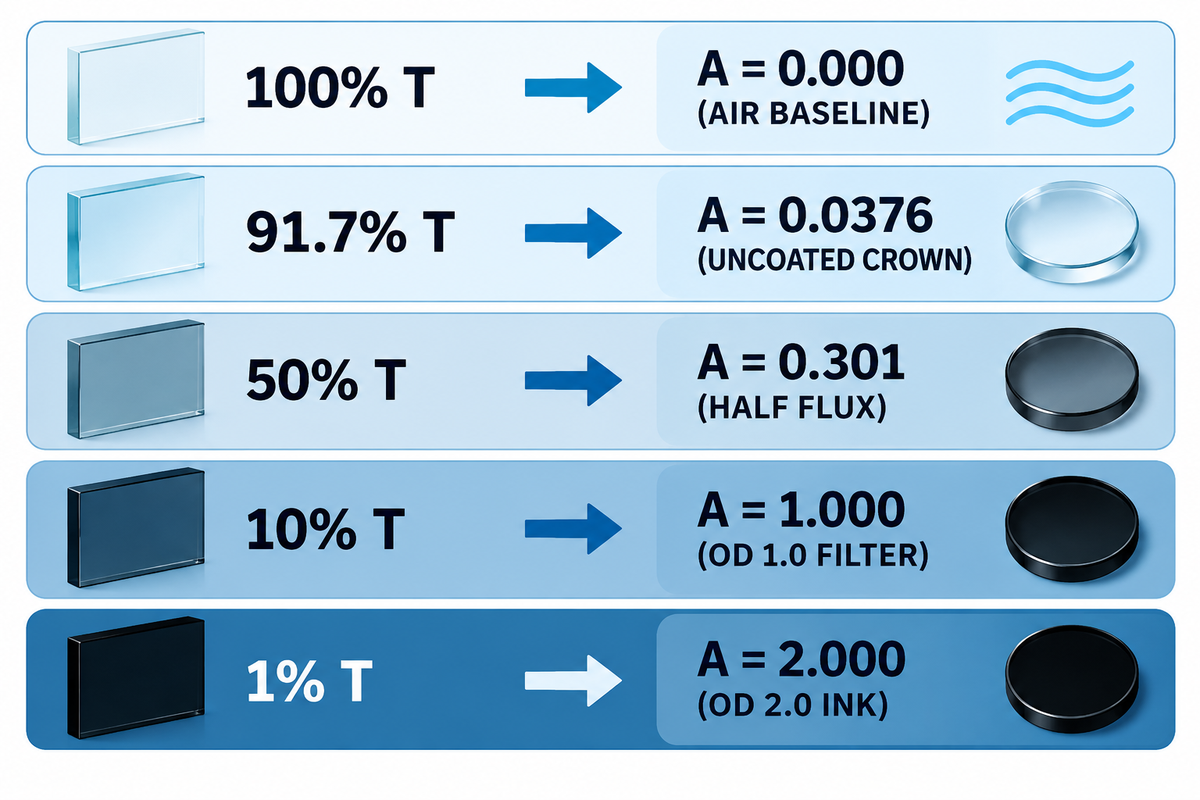
The core transmittance formula links linear optical throughput (T = I / I_0) to logarithmic decadic absorbance (A = −log_10(T)), also called optical density (OD) in neutral-density filter specifications. The transmittance-to-absorbance equation is A = -log10(T) or A = 2 – log10(%T).
- Fractional transmittance equals T = I / I0 for matched radiometric flux or intensity units.
- Percent transmittance equals %T = (I / I0) × 100 on a linear scale from 0% to 100% transmittance.
- A = -log10(T) or A = 2 – log10(%T).
- T = 10^(-A) or %T = 100 × 10^(-A).
Check the order of your fractions when transcribing absorption spectroscopy notes. Inverting the fraction to I0 / I can falsely produce values greater than one (T > 1). In the Beer-Lambert solution, internal absorbance is linearly proportional to path length (l) and concentration. External transmittance with respect to open air is reported for solid glass windows. Experimental absorbance, therefore, includes two reflections at the air/glass interface.
Consider a dual-pane OEM display housing. Stacking two air-spaced uncoated crown glass plates (each at 91.7% normal-incidence transmittance) drops combined throughput to roughly 84.1% (0.917 × 0.917). Apparent experimental absorbance doubles from 0.038 to 0.075 across those four air-glass interfaces, even when bulk absorption is near zero.
| Percent Transmittance (%T) | Fractional T | Decadic Absorbance A = -log10(T) | Typical Glass or Optical Filter Context |
|---|---|---|---|
| 100% | 1.000 | 0.000 | Open-beam 100% air baseline calibration in empty sample compartment |
| 98% | 0.980 | 0.0088 | Multi-layer AR coated optical cover glass threshold (>98% on SW Glass lines) |
| 97.8% | 0.978 | 0.0097 | 0.7 mm Corning Gorilla Glass with double-side 4-layer AR coating |
| 93.2% | 0.932 | 0.0306 | Uncoated UV-grade fused silica lossless Fresnel limit (n ≈ 1.4585, 0°) |
| 91.7% | 0.917 | 0.0376 | Uncoated soda-lime or crown glass first-pass benchmark (n ≈ 1.52, 0°) |
| 80% | 0.800 | 0.0969 | Sputtered ITO + AR conductive coating system near 370 nm UV-blue edge |
| 10% | 0.100 | 1.000 | OD 1.0 neutral density calibration filter |
| 1% | 0.010 | 2.000 | OD 2.0 dark silk-screened border ink; ceiling for 1% stray-light instruments |
| 0.1% | 0.001 | 3.000 | OD 3.0 opaque bezel ink; ceiling for 0.1% stray-light monochromators |
High-density opaque ink testing runs into stray-light bias inside standard instruments. Typical laboratory monochromators carry internal stray light between 0.01% and 1%, depending on wavelength setting and light source (University of Maryland Spectrophotometry Reference). Stray-light levels of 1%, 0.1%, and 0.01% set asymptotic apparent absorbance ceilings at A = 2.0, 3.0, and 4.0, respectively. Target photometric accuracy restricts the usable working range below each instrument’s stray-light ceiling.
Why Does 50% Transmittance Equal 0.301 Absorbance Instead of 0.50?
A 50% transmittance reading is equal to 0.301 absorbance, as transmittance and absorbance are related by a base-10 logarithm rather than linear subtraction. Absorbance is related to transmittance logarithmically, making it a measure of the amount of light attenuated by a sample. When half of the incident light passes through a filter (T = 0.50), absorbance is calculated from transmittance via A = -log10(0.50) = 0.30103. Stacking two identical T = 0.50 filters leaves one-quarter of the transmitted light (T = 0.25) and doubles absorbance to 0.602.
Transmission vs Transmittance vs Transmissivity: Terminology Boundaries
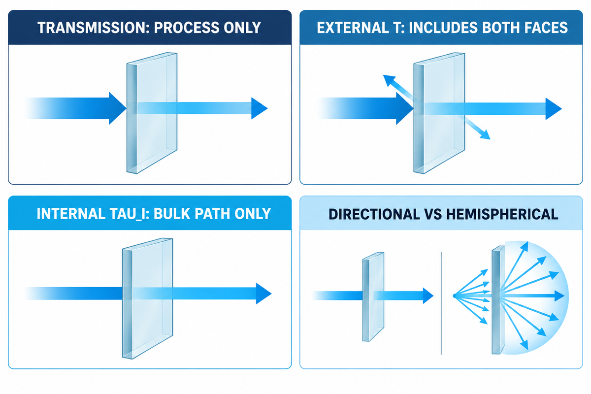
Radiometric standards separate transport processes from specimen-specific ratios. Transmission describes the passage of radiant flux through a medium without implying a numerical ratio. Transmittance (T) expresses the dimensionless ratio of transmitted to incident radiant flux for a specimen, and transmissivity refers to an internal ratio evaluated per unit path under stated conditions.
Internal transmittance (τ_i) ignores air-glass interface reflections across a stated thickness and is dimensionless, unlike the linear attenuation coefficient α (mm^-1). Thinning pane thickness increases transmittance noticeably where bulk absorption is strong, whereas for low-absorption bands the difference is small. Drawings must still specify how much light a material passes at finished thickness instead of copying catalog internal ratios. Confusing linear absorptance (Aabs) with logarithmic absorbance (A) likewise distorts the loss budgets of blue-violet light (<450 nm) versus red (~680 nm) (Physics Forums Spectrophotometry Analysis).
| Term | Symbol & Unit | Includes Surface Reflection? | Thickness Dependent? | Proper Engineering Drawing Usage |
|---|---|---|---|---|
| Transmission | Process only (no unit) | Qualitative | Qualitative | General section headings (such as NIR light transmission window) |
| External Transmittance | T or %T (dimensionless) | Yes (both faces) | Yes | Finished cover glass QC acceptance against 100% air baseline |
| Internal Transmittance | τ_i (dimensionless) | No (bulk path only) | Yes (stated path d) | Optical melt purity comparison at 10 mm catalog reference thickness |
| Transmissivity | Dimensionless internal ratio (definition varies by field) | No (when internal) | Evaluated at stated unit path | Material modeling only when reference path and convention are stated |
| Directional Transmittance | T_r (dimensionless) | Yes | Yes | Unscattered collimated beam acceptance for camera and sensor windows |
| Hemispherical Transmittance | T_h (dimensionless) | Yes | Yes | Integrating-sphere total flux for etched anti-glare or textured glass |
| Absorptance | A_abs (0 to 1 or %) | Linear energy share | Yes | Solar heat gain and high-power laser thermal load budgets |
| Decadic Absorbance | A or OD (logarithmic) | Includes reflection when derived from external T | Internal absorbance scales linearly with path d under Beer-Lambert conditions; external A adds reflection loss | Neutral density filters, laser safety eyewear, and opaque bezel inks |
| Thermal Transmittance | U-factor in W/(m^2·K) | N/A (heat transfer) | Yes (cavity + pane) | Insulating architectural facade units under ANSI/NFRC 100-2026 |
Total vs Internal Transmittance: The Two-Surface Fresnel Loss Budget
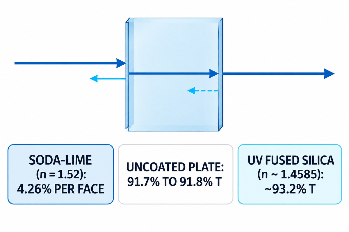
What accounts for uncoated soda-lime or crown glass (n ≈ 1.52) stalling near 91.7% to 91.8% light transmittance at normal incidence? Hardware teams use the Two-Surface Fresnel Loss Budget to separate interface and bulk losses. It adds up attenuation due to boundary reflections at both air-glass interfaces and exponential bulk absorption within the melt.
Consider unpolarized light crossing from air (n0 = 1.00) into an uncoated plate with refractive index of optical glass n at 0° normal incidence. Fresnel equations link single-surface reflectance and lossless plate transmittance directly to refractive index.
At 0° normal incidence, R = [(n – 1) / (n + 1)]^2; for a lossless uncoated plate in air with incoherent internal reflections collected, T_ext = 2n / (n^2 + 1).
For standard soda-lime or crown glass (n ≈ 1.52) under unpolarized normal-incidence light, each face reflects 4.26% of incoming photons. Surface bounce alone limits how much of the light enters the bulk, leaving 91.8% of light getting across a lossless plate (91.7% first pass). Lower-index UV fused silica (n ~ 1.4585) has a reflectance of 3.48% per face and thus reaches ~93.2% uncoated transmittance.
It’s a common assumption that the ~91.8% limit for glasses with n ≈ 1.52 is independent of angle of incidence. In the case of oblique incidence, however, polarization splitting occurs. Transverse-magnetic (p-polarized) reflection drops to zero at Brewster’s angle (about 56.7° for n = 1.52), while transverse-electric (s-polarized) reflection climbs steeply.
How Does Glass Thickness Shift Spectral Transmittance Across 1 mm to 10 mm?
Thinning a homogeneous glass window from 10 mm (τ_i = 0.990) down to 1.0 mm raises internal transmittance to 0.990^(0.1) = 0.9990, while surface Fresnel reflection stays constant. At a fixed wavelength, internal transmittance decays exponentially with path length: τ_i(d2) = [τ_i(d1)]^(d2 / d1). Thick structural viewports compound trace bulk absorption rapidly. Aerospace window modeling by Galuppi and Royer-Carfagni (Advances in Space Research, June 2026) analyzed three-pane borosilicate viewports combining one 9.46 mm debris pane with two 39.14 mm pressure panes. Visible transmittance dropped to 66.7% across that three-pane borosilicate stack (~90% on a thin sheet).
Spectral Light Transmittance Across UV, Visible (VLT), and NIR Wavelengths
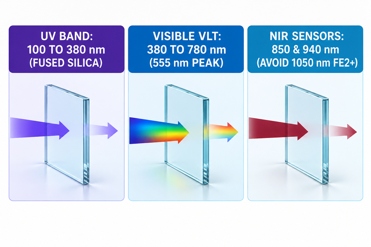
Silicate glasses never transmit equally across different wavelengths because network bonds and trace ions set wavelength-dependent cutoffs. Spectrophotometric glazing standards divide solar energy into ultraviolet (100 to 380 nm), visible light (380 to 780 nm), and infrared (780 to 3000 nm) bands (GlassOnWeb Spectrophotometric Glazing Guide). Match each melt to the type of light your sensor uses.
In the ultraviolet band, silicate bridging oxygens and trace ferric ions create a sharp short-wave cutoff. Ordinary soda-lime float glass drops steeply below 320 nm. High-purity synthetic silica is a primary industrial glass choice for UV-C disinfection optics at 254 nm or 265 nm, alongside crystalline UV windows such as calcium fluoride. Specialty melts instead dope cerium ions to block damaging UV photons in radiation shielding viewports.
Visible light transmittance (VLT) is not an unweighted arithmetic average across 380 to 780 nm. ISO 9050:2026 weights spectral transmittance by human photopic eye sensitivity V(λ) (peaking near 555 nm) under standard illuminant CIE D65. Narrow slices of the visible spectrum are tailored by rare-earth dopants: neodymium glass produces sharp absorption band peaks for wavelength calibration, while trace selenium decolorizes commercial melts.
Near-infrared (ir) and infrared spectroscopy windows hinge on bulk iron redox chemistry and lattice cutoffs. Residual ferrous iron (Fe^2+) creates a broad absorption trough near 1050 nm that spills into 850 nm and 940 nm sensor channels. Mid-IR Fourier-transform infrared spectroscopy cells require halide or chalcogenide crystals. Specifying low-iron silicate glass restores high transmittance in the near-infrared for biometric cameras, optical fibers, and LiDAR enclosures.
Optical and Cover Glass Transmittance by Substrate Material
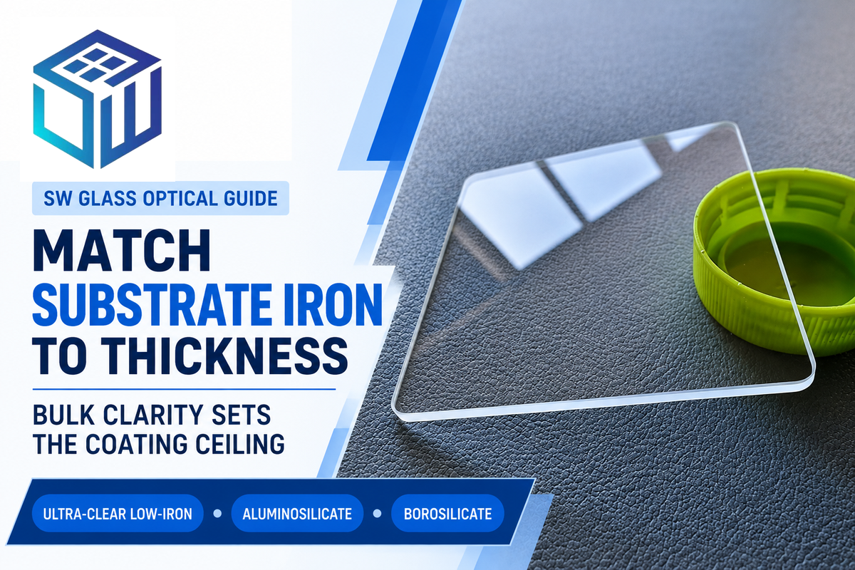
Anti-reflective coatings only reduce air-glass boundary reflection and cannot recover photons already absorbed inside a high-iron substrate. Across this range of materials, bulk iron levels govern the maximum light that can pass through thick viewports. Because datasheets report each glass family at its standard reference thickness rather than in a uniform 2 mm to 6 mm multi-substrate table, engineers compare stated benchmarks and scale path thickness via τ_i(d2) = [τ_i(d1)]^(d2 / d1).
On 0.7 mm automotive touchscreens, chemically strengthened aluminosilicate glass (Corning Gorilla Glass) delivers 92% uncoated transmittance alongside compressive stress above 450 MPa, rising to 97.8% with a double-side 4-layer AR stack. SW Glass supplies annealed low-iron ultra-clear glass specifications in 0.7 mm to 19 mm thicknesses (chemically strengthened up to 2.2 mm or EN 12150 tempered from 3 mm) with ferric oxide (Fe2O3) below 0.015%. At the 6.0 mm ISO 9050 benchmark, low-iron float exceeds 91% VLT versus 83% to 84% for ordinary clear float (0.1% Fe2O3). Thermal and UV instruments rely on custom optical glass solutions in Schott Borofloat 33 or fused silica.
Base optical sheets come from primary melters including Corning, AGC (Dragontrail), Schott, Ohara, and CDGM. Custom cover-glass processors such as Dongguan Saiwei Glass Co., Ltd. (SW Glass) combine CNC shaping, potassium ion-exchange strengthening, and multi-layer AR sputtering, with SW Glass reporting >98% VLT on 1.1 mm Borofloat 33 and double-side AR low-iron panels. Because processors strengthen glass to target optical thicknesses and public vendor catalogs rarely publish cross-brand data at identical strengthened thicknesses, buyers qualify processors via melt certificates and batch spectrophotometer test reports.
| Glass Substrate & Surface Condition | Stated Thickness | Measured Transmittance | Key Optical & Iron Profile | Source / Verification Basis |
|---|---|---|---|---|
| Ordinary Clear Soda-Lime Float (Uncoated) | 6.0 mm | 83% to 84% VLT | 0.1% Fe2O3; visible green edge tint | SW Glass 6 mm ISO 9050 comparison |
| Low-Iron Ultra-Clear Float Glass (Uncoated) | 6.0 mm (supplied 0.7 to 19 mm) | >91% VLT | Fe2O3 <0.015%; eliminates green tint | SW Glass 6 mm ISO 9050 datasheet |
| Low-Iron Glass + Single / Double AR | 0.7 to 19 mm | >94% (1-side) / >98% (2-side) | Reflectivity <1% single-side, <2% double-side | SW Glass vacuum-deposited coating spec |
| Aluminosilicate Corning Gorilla Glass (Uncoated) | 0.7 mm | 92% VLT | Ion-exchange toughened CS >450 MPa, DOL >8 μm | SW Glass automotive display case |
| Aluminosilicate Gorilla Glass + 4-Layer AR | 0.7 mm | 97.8% VLT | Reflection <1%; AF water contact angle >115° | SW Glass double-side AR+AF case |
| Schott Borofloat 33 + Multi-Layer AR | 1.1 mm | >98% VLT | Reflectance <0.5%; CS >700 MPa strengthened | SW Glass medical AR glass specification |
| Borosilicate Glass (Single-Pane Profile) | Thin optical sheet | ~90% VLT | Low thermal expansion; 66.7% across 3-pane Cupola stack | Galuppi & Royer-Carfagni (Adv. Space Res. 2026) |
| UV-Grade Fused Silica Window (Uncoated) | Lossless plate limit | ~93.2% (0° visible) | n ≈ 1.4585; deep-UV to NIR low bulk absorption | Fresnel normal-incidence equation |
When Does Low-Iron Glass Outperform Standard Soda-Lime on Light Transmission?
Low-iron glass delivers its largest optical advantage on thick panels (3 mm to 19 mm), over white back-printed graphics, and beneath multi-layer AR coatings. At the 6 mm ISO 9050 benchmark on SW Glass datasheets, low-iron glass achieves above 91% visible light transmittance versus 83% to 84% for regular clear float glass, carrying a 15% to 25% substrate cost premium. An Alibaba B2B glass pricing guide (Q2 2024 to Q1 2026) lists commodity float at $1.50 to $15/m² and double-glazed low-E at $120 to $150+/m². Custom CNC cover glass is instead quoted per drawing.
How Optical Coatings Change Light Transmittance: AR, AG, and ITO Trade-Offs
Once bulk iron absorption is controlled, thin-film wave interference effects govern the remaining ~8% two-surface reflection budget. Vacuum magnetron sputtering alternates high-index and low-index dielectric oxides so reflected waves cancel destructively, letting multi-layer cover lenses transmit above 98% of visible light. Sputtering is forecast to post the fastest 6.47% CAGR through 2031 in anti-reflective coatings (Mordor Intelligence AR Coatings Report).
Inside SW Glass high-vacuum sputtering chambers (<10^(-3) Pa), multi-layer anti-reflective coated glass achieves >98% transmittance and <0.5% reflectance across 0.5 mm to 12 mm thicknesses. Single-side AR coatings lift low-iron glass above 94% transparency (95% to 97% on standard single-layer AR lines). Touchscreens exposed to grit can pair clarity with hard nitride stacks: granted Corning patent US9726786B2 documents scratch-resistant AR glass maintaining ≤10% post-Taber haze on an 8 mm port Haze-Gard Plus.
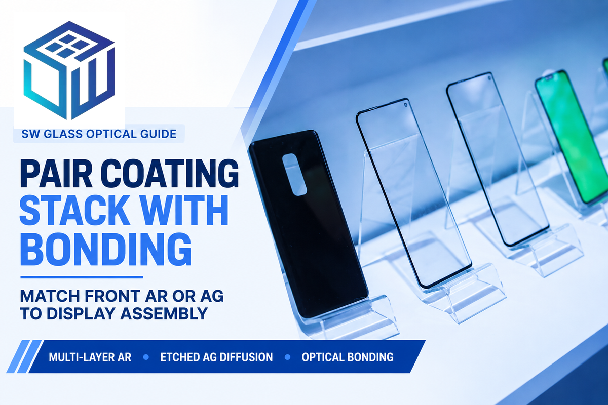
Compare single-sided versus double-sided magnetron-sputtered AR and AF coating capabilities to your display assembly architecture. Double-sided AR increases throughput when an air gap is present between the cover lens and the LCD panel. In an optically bonded module, index-matched OCA or LOCA adhesive (n ≈ 1.49 to 1.51) cures by cross-linking directly against the inner glass surface (LOCA optical bonding guide). That bond removes the rear air interface, so the correct specification is single-sided front AR and rear optical bonding.
Functional surface treatments that trade specular throughput for glare diffusion, cleanability, or EMI shielding include:
- Etched anti-glare cover glass uses controlled surface haze to diffuse specular glare (such as 3% low haze on oil-exposed industrial HMIs), lowering narrow-beam regular readings without necessarily lowering hemispherical flux.
- Fluoropolymer anti-fingerprint (AF) topcoats create a hydrophobic and oleophobic surface with a water contact angle over 115°, keeping reflection below 1% on 4-layer AR+AF cover glass (>97% transmittance).
- Sputtered indium tin oxide (ITO) conductive films span 3.5 Ω/sq to 1 kΩ/sq sheet resistance (3 to 800 Ω/sq on SW Glass low-iron sheets). On 1 mm BK7 at 370 nm, bare sputtered ITO reaches 63.5% transmittance at 30 nm (210 Ω/sq), 66.1% at 51 nm (115 ± 5 Ω/sq), and 61.5% at 111 nm (57 Ω/sq). Adding an underlying AR stack beneath 51 nm ITO on 6.35 mm BK7 lifts 370 nm transmittance to 80% (Jansson et al., PTB/NANEO Preprint).
How to Measure Transmittance: Spectrophotometers, Integrating Spheres, and Standards
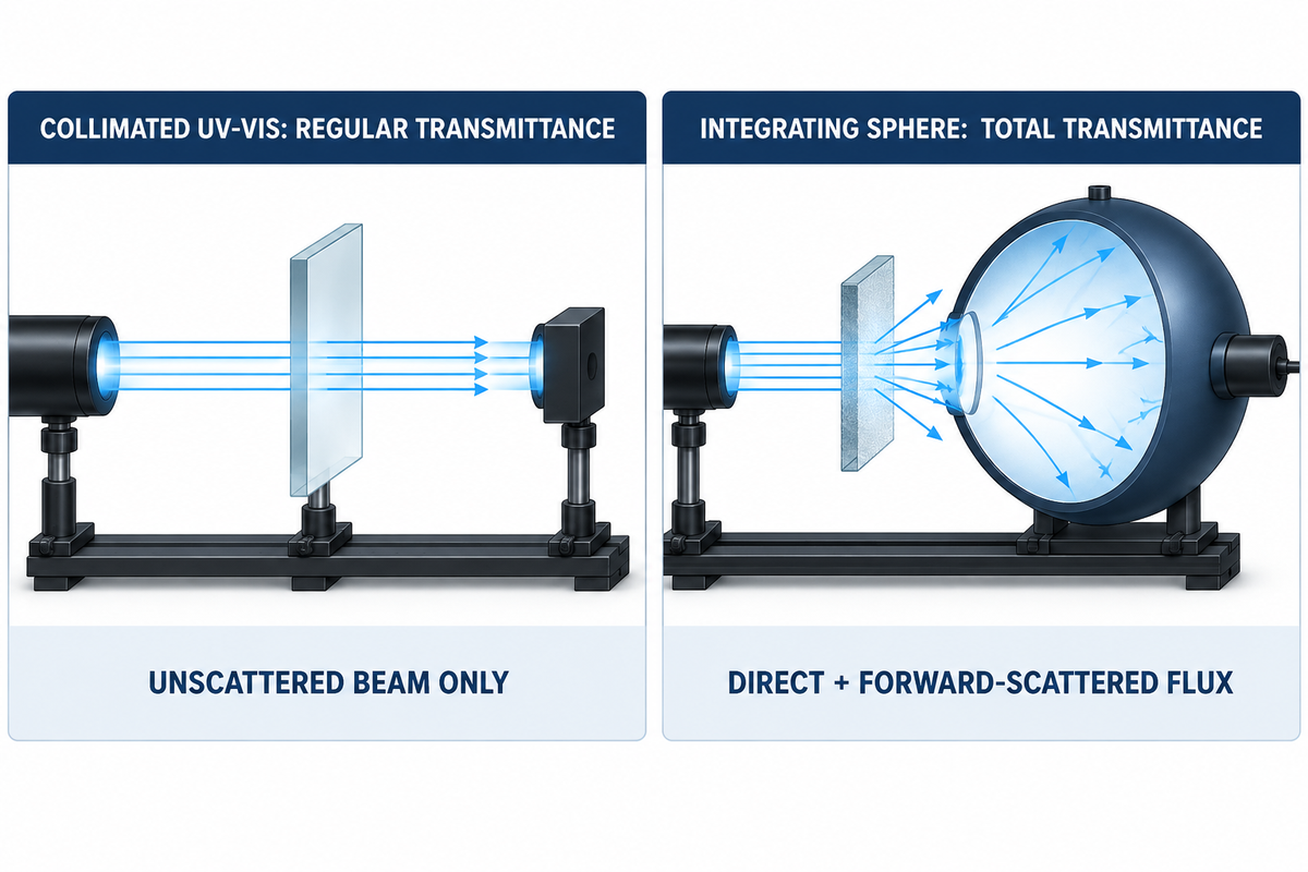
Laboratories measuring transmittance select optical devices according to the acceptance criteria on the drawing. A collimated UV-Vis spectrophotometer is used to measure regular directional transmittance. It tests transparent samples and measures how much of the unscattered transmitted beam reaches the detector. An integrating sphere spectrometer collects both direct and forward-scattered flux for total hemispherical transmittance.
Formally, ASTM D1003 covers haze and luminous transmittance of planar transparent plastics, whereas ISO 13468-1 covers total luminous transmittance of transparent plastics only. Cover-glass QA labs adapt integrating-sphere geometries from these standards, where port ratio, beam size, and sphere compensation influence diffusing samples. At KRISS (Hwang & Baek, Metrologia 2025), a reference double-beam spectrophotometer measured 16.9% haze on a diffusing panel, standing 1.3% higher in haze units than the uncompensated ASTM D1003 result. ASTM E903-20 (300 nm to 2500 nm solar sphere testing) likewise notes special considerations for textured sheet materials.
For flat architectural and industrial glazing, European standard EN 410 and ISO 9050:2026 (Edition 3, published 24 July 2026) produce close luminous and solar results. North American NFRC calculations differ noticeably on Low-E coated glass (OTM EN, ISO, and NFRC Test Method Comparison). Spectral transmittance results collected under the 16-page NFRC 300 method (300 nm to 2500 nm) can be used directly for EN 410 or ISO 9050 calculation, but 1-page ISO 9050 testing records cannot be reversed into NFRC compliance. Edition 3 of ISO 9050 also introduces building-integrated photovoltaic (BIPV) glazing calculations while stating explicit exclusions:
“This document is accordingly applicable to all transparent materials except those which show significant transmission in the wavelength region 5 μm to 50 μm of ambient temperature radiation, such as certain plastic materials.”
Should You Measure AG or Textured Glass with a Regular Beam or an Integrating Sphere?
For etched anti-glare (AG) or textured glass, an integrating sphere collects direct and diffuse transmitted light for total transmittance measurements; a collimated-beam setup measures regular transmittance. Due to variation in port ratio and compensation geometry, state the test standard and port aperture diameter on the drawing.
Specifying Light Transmittance on Custom Cover Glass Drawings
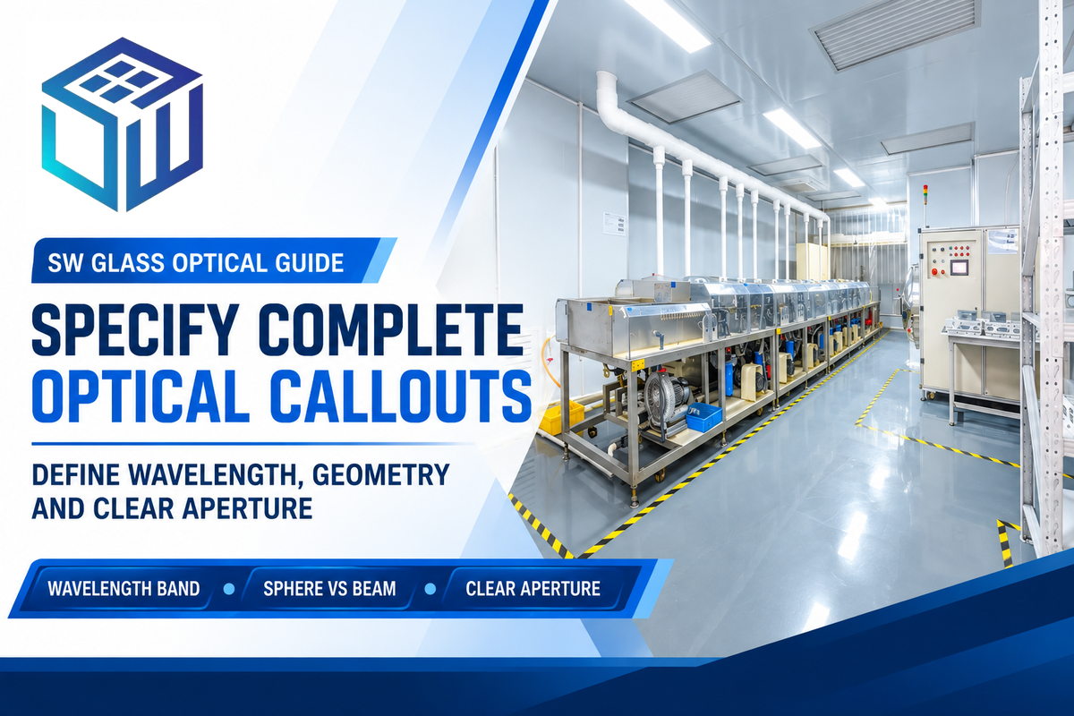
Writing just “Transmittance ≥ 92%” on a CAD print can lead to disputes with vendors and mismatched incoming inspection fixtures (see the cover glass drawing specification checklist). Use the following 5-Field Transmittance Drawing Rule when releasing prints for custom display cover glass fabrication.
- Define wavelength point versus weighted band. State whether acceptance applies to a 550 nm peak, D65-weighted VLT (380 to 780 nm per ISO 9050:2026 or EN 410), or discrete 850 nm and 940 nm NIR sensor channels.
- Name the measurement techniques and collector geometry: regular collimated transmission spectroscopy for directional acceptance, or integrating-sphere hemispherical measurement (with stated standard and port aperture) for total transmittance.
- Fix the incidence angle and polarization state, defaulting to 0° normal incidence with unpolarized light while specifying exact off-axis cone angles for tilted LiDAR hoods.
- Mark a clear-aperture test location on the schematic diagram well inside silk-screened black borders so sample preparation holders never clip opaque ink edges.
- Separate instrument photometric uncertainty from lot acceptance tolerance against a 100% air baseline. SW Glass CNC-cuts 0.5 mm to 12 mm AR panels from 10 × 10 mm to 2000 × 1500 mm (MOQ 100 pieces; standard lead time 7 to 15 days, rush 5 to 7 days). Every shipment includes spectrophotometer quality inspection data holding batch-to-batch AR variation to ±0.3%, with pricing quoted per RFQ.
Frequently Asked Questions About Transmittance
How do you convert percent transmittance (%T) to absorbance in spectrophotometry?
Convert percent transmittance to decadic absorbance using the base-10 equation A = 2 – log10(%T) or A = -log10(T) when starting from fractional transmittance.
To reverse the calculation from absorbance to transmittance, compute T = 10^(-A) and multiply by 100 for %T. Exact logarithmic checkpoints are T = 1.00 (100% air baseline, A = 0.000), T = 0.50 (50%, A = 0.301), T = 0.10 (10%, A = 1.000), and T = 0.01 (1%, A = 2.000) subject to monochromator stray-light limits at high optical density.
Why is uncoated soda-lime or crown glass capped near 91.7% to 91.8% light transmittance at normal incidence?
Uncoated soda-lime and optical crown glass (n ≈ 1.52) stall near 91.7% to 91.8% transmittance at 0° normal incidence because each air-glass interface reflects 4.26% of unpolarized visible light.
Lower-index uncoated UV fused silica (n ≈ 1.4585) approaches approximately 93.2% throughput at normal incidence, provided that bulk absorption is negligible. For the n ≈ 1.52 soda-lime or crown-glass baseline, going beyond this uncoated Fresnel limit would require the use of either single- or multi-layer anti-reflective coatings, or index-matched optical bonding, to reduce surface reflections.
What is the difference between single-wavelength 550 nm transmittance and average visible light transmittance (VLT)?
Single-wavelength 550 nm transmittance measures throughput at one green peak, whereas visible light transmittance (VLT) weights the full 380 to 780 nm band.
Under ISO 9050:2026, EN 410, and ANSI/NFRC 200-2026, VLT integrates spectral data against CIE D65 solar illumination and human photopic eye sensitivity. Because narrowband anti-reflective coatings roll off toward violet and red edges, any offset between peak 550 nm readings and weighted VLT must be integrated from the full spectral curve.
Can optical transmittance ever exceed 100% in a spectrophotometer reading?
Yes, it’s possible for apparent spectrophotometer readings to exceed 100% due to baseline drift, sample fluorescence, or a mismatched blank.
Zeroing on an uncoated glass blank before testing an AR-coated cover lens can push apparent transmittance above 100%, although passive physical transmittance never exceeds 100%.
Does chemical strengthening change the light transmittance of aluminosilicate or soda-lime cover glass?
For glass strengthened by potassium nitrate (KNO3) ion exchange to a compressive stress above 450 MPa, bulk visible light transmittance can remain virtually unchanged.
Ultrasonic cleaning prior to vacuum AR coating removes contamination. The substrate’s iron content and the uniformity of the coating affect transmittance in finalized glass.
What transmittance specification applies to NIR 850 nm and 940 nm LiDAR or IR sensor cover windows?
Near-infrared LiDAR and camera windows pair low-iron, aluminosilicate, or fused silica substrates with AR stacks tuned specifically to 850 nm, 905 nm, or 940 nm.
Eliminating ferrous iron avoids the 1050 nm bulk absorption band, and concealed sensor bezels must define both NIR passband transmittance and visible optical density on the inspection print.
How does optical bonding improve display assembly transmittance compared with an air gap?
Index-matched OCA or LOCA adhesive (n ≈ 1.49 to 1.51) eliminates two internal air-glass Fresnel reflections.
Removing the internal air gap recovers approximately 8% transmitted display brightness and improves contrast for outdoor sunlight.
About This Optical Engineering Reference
This transmittance guide combines radiometric standards (ISO 9050:2026, EN 410, ASTM D1003, and ASTM E903-20) with production coating and substrate benchmarks from SW Glass’s magnetron-sputtering, CNC fabrication, and spectrophotometer inspection lines. Reviewed by the Dongguan Saiwei Glass Co., Ltd. technical team.
References & Sources
- ISO 9050:2026, Glass in building: Determination of luminous and solar characteristics of glazing (Edition 3, July 2026)
- Standards Norway, ISO 9050:2026 Scope, BIPV Methodology, and Far-IR / VIG Exclusions
- Hwang, J. & Baek, S. (2025). Comparison of haze and luminous transmittance measurement methods under ASTM D1003 and ISO 13468, Metrologia 62, 065005
- Galuppi, L. & Royer-Carfagni, G. (2026). Thermo-optical transmittance of multi-pane borosilicate and fused silica windows, Advances in Space Research
- O’Haver, T., Beer-Lambert Law, Absorbance Linearity, and Monochromator Stray Light Ratings (University of Maryland)
- Harper College Department of Chemistry, Spectrophotometry: Transmittance (%T) and Absorbance Principles
- Jansson, M. et al., Combined Anti-Reflective and Sputtered ITO Optical Coatings on BK7 Glass (PTB & NANEO Precision Optics, arXiv:2411.10361v1)
- US Patent US9726786B2, Scratch-Resistant Optical Glass Articles with Anti-Reflective Coating and Haze Metrology (Corning Inc.)
- Pacific Northwest National Laboratory (PNNL), High-Performance ENERGY STAR Most Efficient Window U-Factor Criteria
- OTM Solutions, Comparison of EN 410, ISO 9050, and NFRC 300 Glazing Spectral Transmittance Test Methods
- GlassOnWeb, Specification of Glazings in Facades Based on Spectrophotometric Characterization of Transmittance
- Mordor Intelligence, Anti-Reflective Coatings Market Deposition Share & Sputtering Forecast (2025–2031)
- Physics Forums, Physical Distinction Between Linear Absorptance and Logarithmic Absorbance in Spectrophotometry
- Alibaba Electronics Buying Guide, B2B Flat Glass and Double-Glazed Low-E Price Benchmarks (Q2 2024 – Q1 2026)