Get in Touch with Saiweiglass



Ultrasonic machining (USM) is a non-thermal subtractive manufacturing process that employs a high-frequency vibration and fine abrasive particles to remove material from hard and brittle workpieces. A tool oscillates between 18 kHz to 40 kHz and 10 µm to 50 µm in abrasive slurry (Lehigh University). A rotating diamond core vibrates axially at 1 µm to 16 µm to drive micro-brittle fracture without electrical arcs or heat-affected zones.
This machining process is typically used for silicate optical glasses, fused silica, aluminosilicate cover glass, technical ceramics, and hardened alloys above 40 HRC. For deep round bores, use rotary tooling and for micro-hole arrays, use slurry tooling.
Quick Engineering Baseline
Acoustic envelope: 18 kHz to 40 kHz ultrasonic frequency; 10 µm to 50 µm slurry stroke or 1 µm to 16 µm rotary diamond amplitude.
Eligible substrates: Silicate glasses (0.7 to 1.0 MPa√m fracture toughness), technical ceramics (1,200 to 2,400 HV), and hardened steels above 40 HRC.
Typical glass output: Matte ground surface finish around 0.2 µm to 1.6 µm Ra. Bore tolerances hold ±0.010 mm to ±0.025 mm under controlled ultrasonic finishing, and ±0.05 mm on 0.5 mm to 80 mm production holes.
For non-circular blind cavities, and internal corners, slurry USM is preferred over rotary tooling. For multi-pin micro-hole arrays in glass, slurry USM is preferred. Rotary ultrasonic machining (RUM) employs a diamond core drill, with axial vibration, and through spindle coolant to cut ceramic composites roughly 10 times faster than USM. All holes, slots, and bevels must be machined before thermal tempering or chemical strengthening.
Key Takeaways for Design and Procurement
- Loose abrasive slurry USM and bonded-diamond rotary ultrasonic machining use distinct tools, fluids, and dimensional offset rules.
- Hole oversize in stationary slurry sinking scales roughly at twice the mean diameter of the abrasive grain.
- In a 2024 fused silica deep-drilling study, helical ultrasonic oscillation reduced maximum bore diameter deviation by over 91% when compared to the same grinding process without ultrasonic.
- Standard 3-axis CNC diamond drilling remains faster and more economical for routine round holes from 2 mm to 80 mm in flat cover glass.
What Is Ultrasonic Machining and How Does It Remove Brittle Material?
The working principle of the ultrasonic machining process relies on the micro-brittle fracture rather than shear chip formation or thermal melting. Think of it as microscopic sandblasting driven by a shaped hammer across a thin liquid film. A vibrating tool oscillates vertically with high-frequency vibrations at 18 kHz to 40 kHz while feeding gently toward the workpiece surface. Water based abrasive slurry flows continuously through the narrow space between the tool and workpiece.
Each descending stroke strikes thousands of suspended abrasive particles against the brittle surface of the workpiece. Localized impacts of this nature initiate microscopic radial and lateral cracks, which eventually dislodge tiny granules. Cavitation bubbles assist in the removal of debris in the abrasive slurry. Direct mechanical hammering still performs the primary work in the brittle material removal process.
Because the cutting tool never relies on electrical conductivity or arc melting, the workpiece remains near ambient temperature. Amorphous silicate glasses retain their stress-free internal network, hence no recast layers and thermal microcracking. On the other hand, ductile metals softer than 40 HRC absorb the impact of abrasive particles via plastic deformation and reduce removal rates to less than 10 mm³/min.
What are the four main elements of ultrasonic machining?
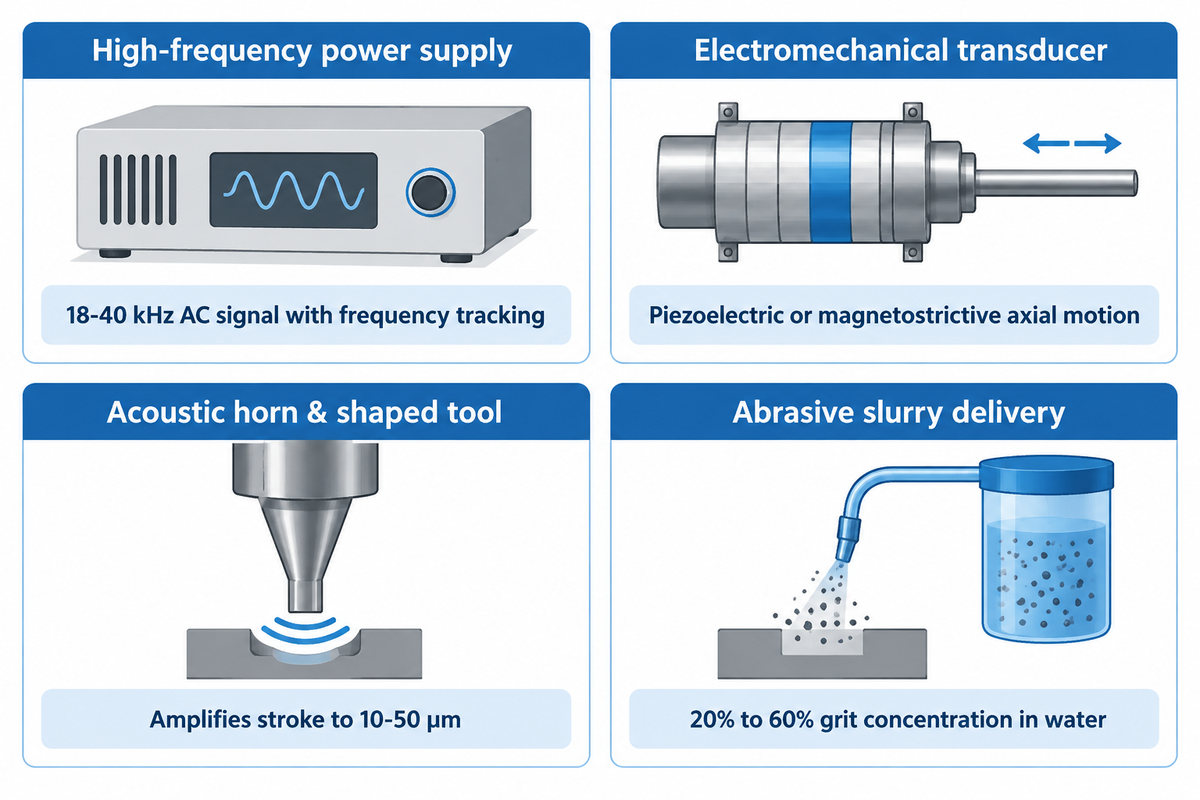
Each stationary ultrasonic machine tool consists of four synchronized subsystems: a high-frequency power supply, an electromechanical transducer, an acoustic horn (sonotrode), and a chilled slurry delivery unit. If acoustic resonance drifts across the horn and brazed tool tip, vibration amplitude drops sharply and machining efficiency stalls.
| Subsystem | Engineering Function | Design & Maintenance Constraint |
|---|---|---|
| High-frequency power supply | Converts 50/60 Hz mains power into 18–40 kHz AC signal | Requires automatic frequency tracking as tool wear shifts mass |
| Electromechanical transducer | Converts electrical oscillation into low-amplitude axial motion | Two types of transducers exist: piezoelectric crystals (cooler operation) vs. magnetostrictive stacks (require cooling) |
| Acoustic horn & shaped tool | Amplifies stroke to 10–50 µm and transfers cavity profile | Tuned to half-wavelength resonance; ductile stainless steel or titanium resists fatigue |
| Abrasive slurry delivery | Supplies boron carbide, silicon carbide, or aluminum oxide in water | Maintains 20% to 60% weight concentration and chills fluid against cavitation vapor lock |
The recent shift toward piezoelectric transducers in ultrasonic machining technology tools, as opposed to the older nickel-stack magnetostrictive units, is due to the fact that piezoelectric crystals run cooler and help maintain tighter amplitude stability. New ultrasonic power generators also automatically track shifts in resonant frequency as tool tips wear. It’s worth mentioning that industrial ultrasonic machining tools are completely different from a handheld ultrasonic cutting machine, used for slicing polymers, textiles, and food, without the need for abrasive grit.
Conventional Slurry USM vs. Rotary Ultrasonic Machining (RUM)
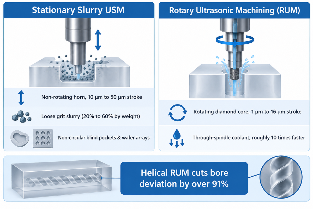
Conventional ultrasonic machining and rotary ultrasonic machining differ in tool kinematics, abrasive bonding, and evacuation of deep-bore chips. The traditional ultrasonic machining technique uses loose abrasive slurry to sink inverse cavities and oscillates a shaped tool that is non-rotating. Rotary ultrasonic machining spins a metal-bonded diamond core tool, commonly at 1,000 rpm to 10,000 rpm, while vibrating axially with clean coolant (Zhang et al., Kansas State University). Pushing long hollow drills to higher speeds risks lateral tool whip.
On production display panels where standard round holes don’t call for custom slurry horns, precision CNC glass machining uses diamond core tools and ultrasonic hollow drills to hold ±0.05 mm hole accuracy.
Stationary Slurry USM (Impact Grinding)
- Kinematics: 1-dimensional axial vibration, 0 rpm; tool never rotates.
- Cutting medium: Loose boron carbide or silicon carbide grit in water (20% to 60% by weight).
- Best Geometry: Non-circular holes and blind square pockets; multi-pin wafer arrays.
- Depth bottleneck: Slurry starvation and sidewall erosion add conicity in deep cavities.
Rotary Ultrasonic Machining (RUM)
- Kinematics: Simultaneous spindle rotation and 20 to 30.5 kHz Z-axis vibration.
- Cutting medium: Impregnated diamond grains bonded to a hollow core drill with clean coolant.
- Best geometry: Deep round holes, precision ultrasonic milling of slots, core trepanning.
- Speed advantage: Achieves about a tenfold drilling speed gain over stationary slurry sinking on ceramic composites.
In peer-reviewed drilling experiments on ceramic matrix composites, Z.C. Li and colleagues showed that RUM drills are roughly 10 times faster than traditional slurry USM (International Journal of Machine Tools and Manufacture, 2005). It creates small deep bores with less cutting forces. The diamond abrasive material stays locked on the rotating ring, and the application of ultrasonic vibrations reduces grinding friction and helps maintain the cutting edge. High-pressure internal coolant flushes glass swarf upward without loose grit abrading the upper bore wall.
| Comparison Factor | Stationary Slurry USM | Rotary Ultrasonic Machining (RUM) |
|---|---|---|
| Tool material | Ductile mild steel, 304 stainless steel, or titanium horn | Metal-bonded or electroplated diamond hollow core tool |
| Typical axial amplitude | 10 µm to 50 µm peak-to-peak | 1 µm to 16 µm axial oscillation |
| Fluid & abrasive supply | External nozzle or suction pumping of loose abrasive slurry | Through-spindle clean water or water-soluble grinding coolant |
| Odd-shaped blind cavities | Directly sinks hex, rectangular, and stepped cavities in one plunge | Requires CNC toolpath interpolation; internal corner radius equals tool radius |
| Cutting force on thin glass | Very low static feed load across the slurry gap | Significantly lower axial thrust force than non-ultrasonic diamond grinding |
| Primary dimensional drift | Longitudinal sonotrode tip wear and entry bell-mouth conicity | Lateral whip on long thin drills above 20,000 rpm |
Cranking spindle speed or ultrasonic power to maximum actually degrades deep glass bores. In 2024 fused silica tests on a DMG Mori Ultrasonic 20 linear center, spindle speeds above 20,000 rpm caused lateral whip and severe top edge chipping (Henkel et al., 2024). Setting the speed to 2,000 rpm and using a short pilot bore to stabilize the cut helped alleviate lateral whip.
Maximum diameter deviations can be reduced by over 91% compared to an identical grinding process without ultrasonic tool vibration.
That 40 mm fused silica study also exposed an important kinematic split. In direct plunge deep-hole drilling, wall roughness was roughly 17% better without ultrasonic oscillation. In helical deep drilling, however, active ultrasonic vibration cut maximum bore diameter deviation by over 91%. Specify rotary helical kinematics whenever tight bore cylindricity outweighs raw plunge speed.
Process Parameters, Tolerances, and Surface Roughness on Optical and Cover Glass
Realistic ultrasonic machining tolerances on optical and display glass run from ±0.010 mm to ±0.025 mm under controlled finishing passes. Xometry reports a general 0.005 mm to 0.025 mm process capability, with ground surface finish spanning 0.2 µm to 1.6 µm Ra. Machining parameters are the controllable process settings: vibration frequency, axial amplitude, abrasive grit size (10 µm to 150 µm), slurry concentration, feed force, and spindle speed. Coarse 100 µm to 150 µm grit accelerates roughing to remove material rapidly. Fine 10 µm to 30 µm grit improves surface quality to 0.2 µm to 0.4 µm Ra while limiting subsurface damage depth (Suratwala et al., Lawrence Livermore National Laboratory).
Never assume an ultrasonic pass leaves an optically transparent window wall. Loose slurry impact erosion and diamond rotary ultrasonic grinding create a matte surface texture, which scatters light, unless it’s etched or polished.
The Grit-to-Overcut Clearance Rule
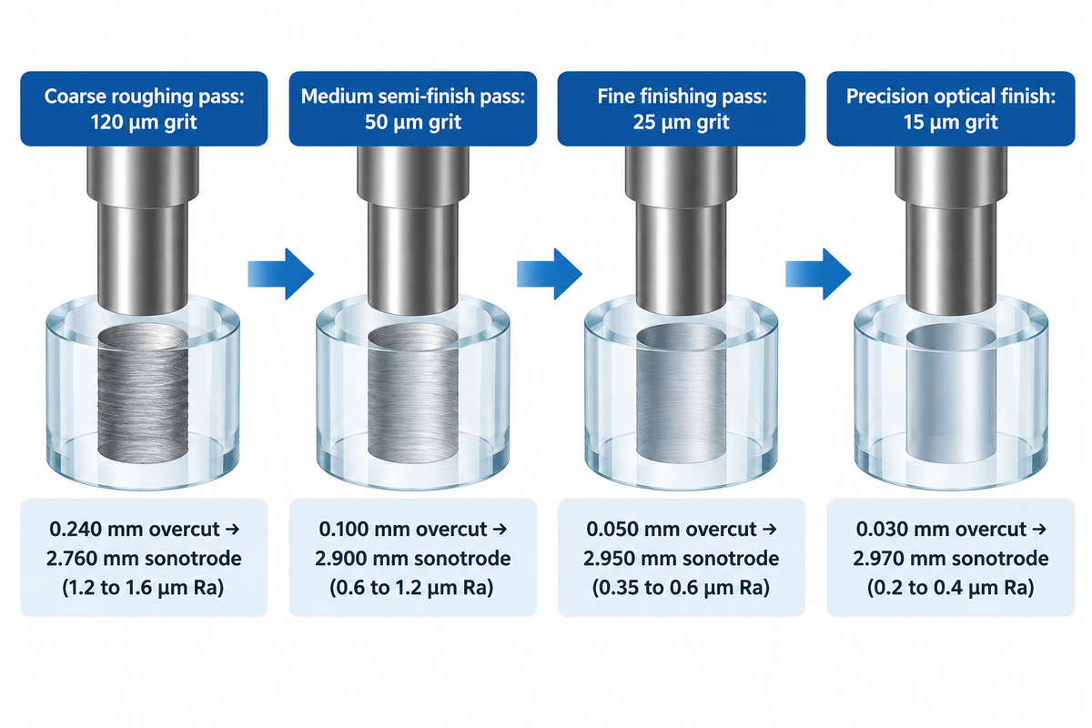
The Grit-to-Overcut Clearance Rule says the effective diameter of a stand-alone USM sonotrode is the target glass bore diameter minus twice the mean diameter of the abrasive particles.
Accuracy studies cited by Henkel et al. (Jadoun et al., 2009) found that stationary ultrasonic hole oversize is approximately twice the average diameter of the abrasive grit used. Assumed inputs: a 3.000 mm target through-hole in annealed borosilicate glass, silicon carbide grit sizes inside the standard 10 µm to 150 µm operating band, and zero spindle runout. For a 15 µm (0.015 mm) finishing grit, two radial grit gaps add 2 × 0.015 mm = 0.030 mm overcut, so a 2.970 mm sonotrode cuts near 3.000 mm.
| Machining Pass Stage | Assumed Mean Grit Size | Calculated Overcut (2× Grit) | Starting Sonotrode OD | Target Glass Ra Regime |
|---|---|---|---|---|
| Coarse roughing pass | 120 µm (0.120 mm) | 0.240 mm | 2.760 mm | 1.2 µm to 1.6 µm Ra |
| Medium semi-finish pass | 50 µm (0.050 mm) | 0.100 mm | 2.900 mm | 0.6 µm to 1.2 µm Ra |
| Fine finishing pass | 25 µm (0.025 mm) | 0.050 mm | 2.950 mm | 0.35 µm to 0.6 µm Ra |
| Precision optical finish | 15 µm (0.015 mm) | 0.030 mm | 2.970 mm | 0.2 µm to 0.4 µm Ra |
The 0.030 mm overcut in this example is a first article tooling offset. Keep in mind, the entry to exit flow of slurry erodes the hole mouth longer than the bottom, thus, many shops do a roughing horn pass followed by a finishing pass.
What frequency is ultrasonic machining?
Industrial ultrasonic machining systems operate between 18 kHz and 40 kHz, at or above the upper limit of human hearing. To maximize horn stroke, heavy-duty slurry sinkers are designed to run at or near 20 kHz. Rotary diamond spindles and drilling at 20 to 40 kHz use 1 µm to 16 µm amplitudes to protect delicate micro-tools.
Micro-Holes, Blind Cavities, and Substrate Behavior Across Glass and Ceramics
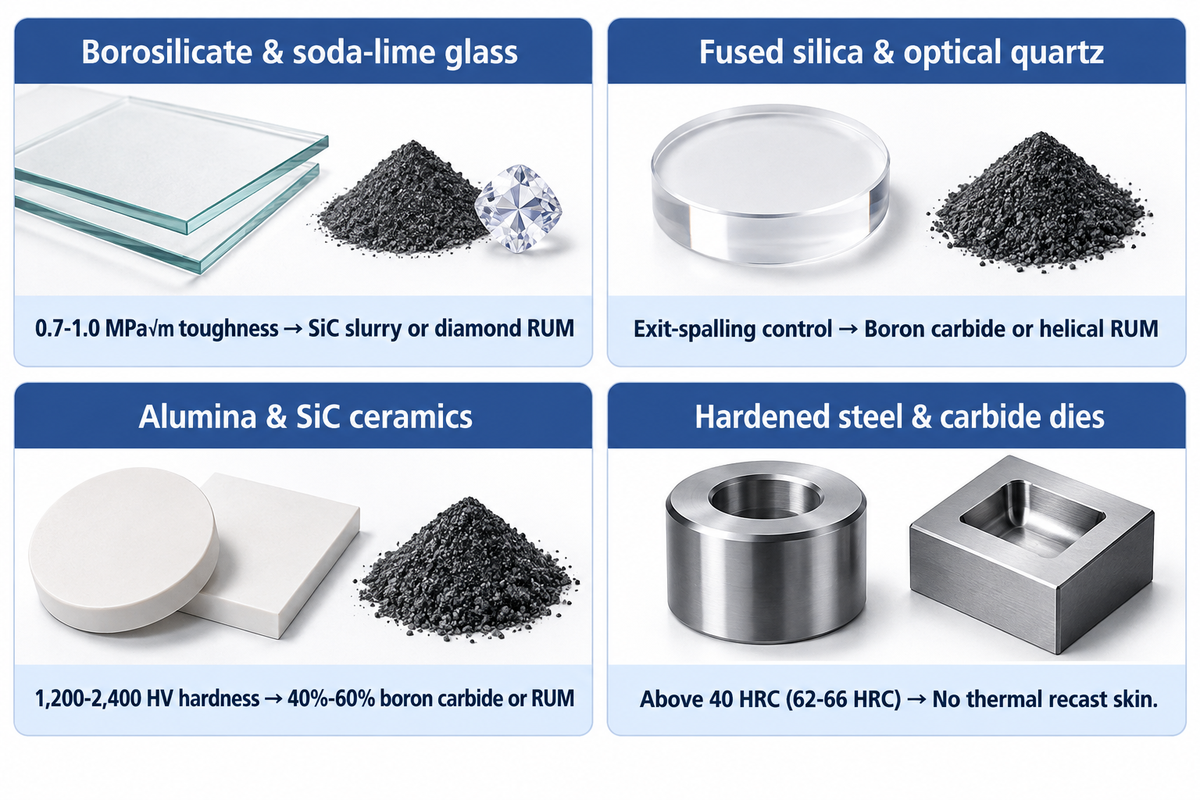
Key material properties, especially fracture toughness below 5 MPa√m and high indentation hardness, govern both abrasive selection and removal speed during the machining of advanced materials. Brittle advanced materials such as silicate glasses and technical ceramics are difficult to machine with standard metalworking cutters because high tool pressure causes edge spalling. Low-toughness glasses (0.7 to 1.0 MPa√m) cut quickly with silicon carbide grit, while ceramics (1,200 to 2,400 HV) require boron carbide or diamond tools (Patwardhan, University of Nebraska-Lincoln).
Using boron carbide or silicon carbide correctly ensures efficient cycles. Silicon carbide cuts soda-lime and borosilicate glass substrates and raw aluminosilicate cover glass economically. When the workpiece approaches silicon carbide’s hardness, abrasive grains dull quickly; switching to harder boron carbide slurry or bonded diamond restores cut speed.
| Workpiece Material | Fracture & Hardness Regime | Preferred Abrasive / Tooling | Typical Machined Features |
|---|---|---|---|
| Soda-lime & low-iron glass | 0.7–1.0 MPa√m toughness; fast micro-chipping | Silicon carbide slurry or diamond RUM | Sensor apertures, switch cutouts, stepped bevels |
| Borosilicate glass | 0.7–1.0 MPa√m toughness; low thermal expansion | Fine SiC / Al2O3 slurry or diamond RUM | Microfluidic channels, MEMS vias, sight-glass steps |
| Raw aluminosilicate cover glass | Higher modulus; sensitive to subsurface flaws | Fine 10–30 µm SiC grit or low-force RUM | Pre-ion-exchange camera bores, microphone micro-slots |
| Fused silica & optical quartz | High-purity amorphous silica; prone to exit spalling | Boron carbide slurry or helical diamond RUM | Lightweighting mirror pockets, deep optical bores |
| Alumina & silicon carbide ceramics | 1,200–2,400 HV hardness; elevated tool wear rate | 40%–60% boron carbide slurry or diamond RUM | Semiconductor wafer chucks, insulator thru-vias |
| Hardened steel & tungsten carbide | Above 40 HRC (62–66 HRC tool steels; 1,800–2,400 HV carbides) | Boron carbide finishing slurry or hybrid RUM | No-recast die cavities where EDM heat skin is banned |
| Single-crystal sapphire & ruby | Anisotropic hardness above alumina; slow slurry erosion | Metal-bonded diamond RUM or coarse-to-fine boron carbide | IR sensor domes, high-pressure optical sight windows |
| Zirconia & silicon nitride ceramics | 1,200–2,000 HV hardness; higher fracture toughness (<4 MPa√m) | Rotary diamond core tools with high-pressure internal coolant | Ceramic bearing races, medical implants, fuel-nozzle bores |
| Monocrystalline silicon & piezoelectric quartz | Cleavage-plane sensitivity; low clamping load required | 10–30 µm fine slurry multi-pin horn (Ra 0.2–0.4 µm) | Wafer resonator cavities, piezoelectric sensor housings |
Real production applications of ultrasonic machining match tool architecture to batch geometry. Machinists on Practical Machinist have produced over 1,000 quartz slides using fine-abrasive ultrasonic drills to make micro apertures without edge flaking. Conversely, on an 8 mm marine instrument window, ultrasonic spindle holders allow efficient machining of stepped O-ring counterbores and flush glass swarf cleanly.
Why Ultrasonic Machining Must Precede Chemical Strengthening and Tempering
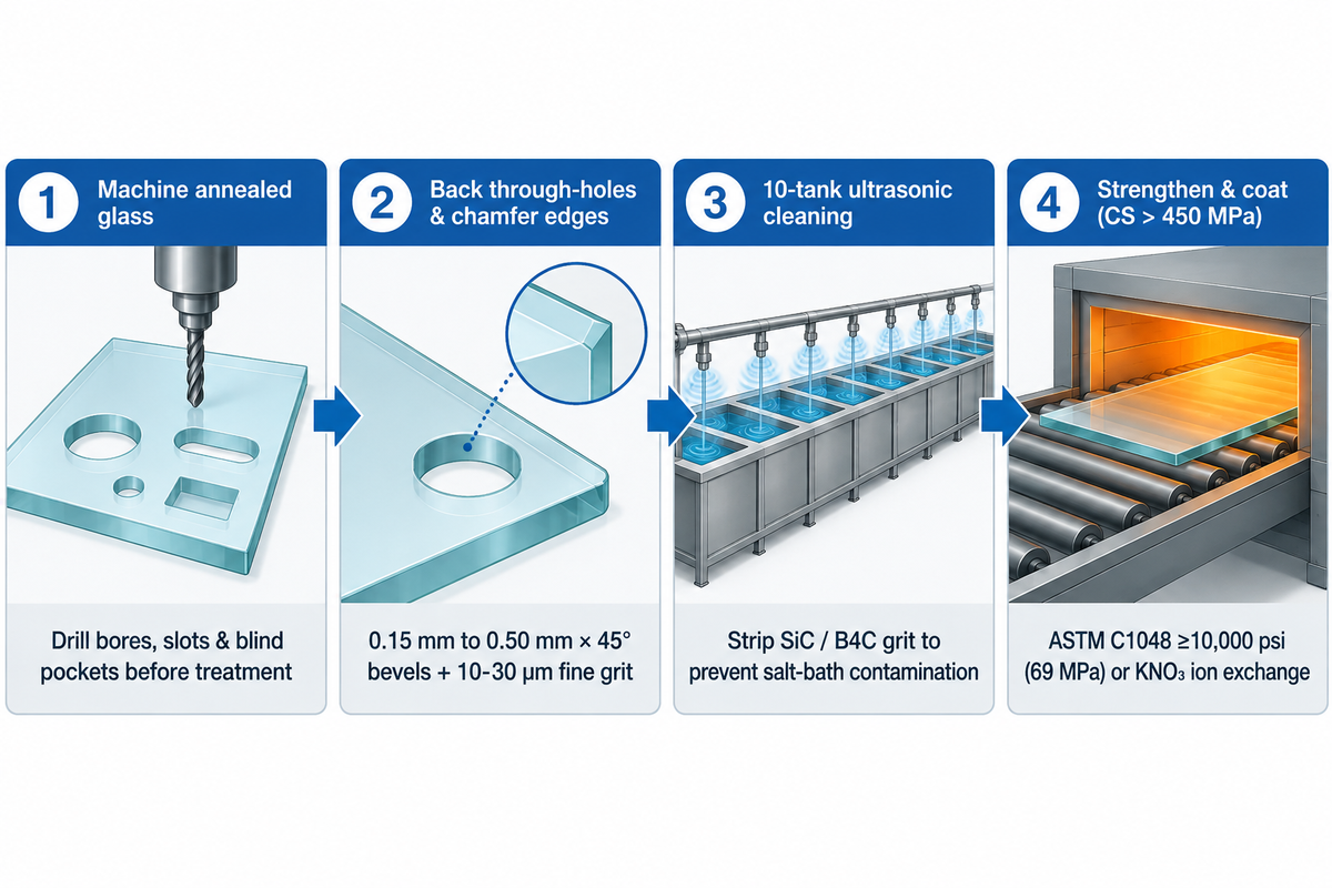
Every ultrasonic drilling, slotting, pocket milling, and beveling step must be completed on annealed raw glass before thermal tempering or chemical strengthening (National Glass Association FB45-14). Both strengthening processes lock the outer surfaces in a balanced compression/tension state. Edge cuts or panel cuts post strengthening would lead to a panel failure.
ASTM C1048 states that fully tempered glass must have a surface compression of at least 10,000 psi (69 MPa). In a tempered lite, high compression balanced by tension extends roughly 20% of the glass thickness into each face until cutting releases unbalanced tension. This stored elastic energy instantly transforms the glass into thousands of tiny pieces.
In contrast, chemical strengthening exchanges larger potassium ions for sodium ions in a molten salt bath (Egboiyi, Michigan Technological University). Ion-exchange cover glass typically forms a 30 µm to 120 µm depth of layer (with SW Glass production verified above 450 MPa CS and 8 µm DOL). Drilling after the salt bath severs that shallow compressive skin around the bore and introduces strength-limiting edge flaws.
Do: Pre-Strengthening Sequence
- Machine all bores, blind pockets, and notches while the glass is annealed.
- Bond a sacrificial glass backing plate to cover through-holes to prevent breakout spalling.
- Add 0.15 mm to 0.50 mm × 45° entrance and exit chamfers to remove edge chips. Give the ion-exchange compressive layer a continuous, flaw-free edge.
- Run 10-tank ultrasonic cleaning to strip residual silicon carbide or boron carbide grit prior to the KNO3 bath.
Avoid: Post-Machining Pitfalls
- Never specify post-temper drilling for late sensor or mounting-hole engineering changes.
- Avoid aggressive feed rates at drill exit, which promotes deep median subsurface cracks.
- Never load unwashed, ultrasonically machined parts into an ion-exchange salt bath, which contaminates the melt.
Abrasion creates subsurface microcracks (American Ceramic Society). In studies on fused silica by DOE OSTI (Suratwala et al.), subsurface mechanical damage showed cracks of various depths corresponding to different grit sizes of abrasive. Finishing with 10 µm to 30 µm grits or acid flash-etching blunts crack tips before strengthening.
Ultrasonic Machining vs. CNC Diamond Grinding, Laser, Waterjet, and EDM
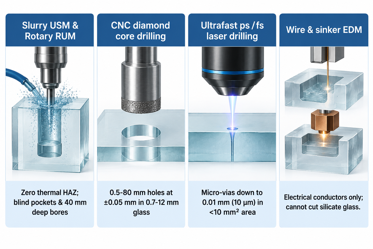
Ultrasonic removal of glass and ceramic features has several advantages over traditional machining and newer machining methods including laser ablation, water jetting and electrical discharge machining. For machining materials like glass and ceramic, engineers evaluate workpiece conductivity, heat-affected zone, edge chipping, and each process’s blind-cavity machining capabilities. Ultrasonic machining wins on blind cavities and micro-hole arrays, whereas CNC diamond drilling wins on routine cover-glass holes above 2 mm.
Brittle-Feature Process Selection Matrix
The Brittle-Feature Process Selection Matrix classifies nine subtractive process categories based on workpiece conductivity, heat affected zone, edge chipping, feature scale, and primary geometric sweet spot.
| Process Type & Category | Workpiece Conductivity | Heat-Affected Zone (HAZ) | Edge Chipping Regime | Feature Capability | Primary Geometric Sweet Spot |
|---|---|---|---|---|---|
| Stationary slurry USM (loose-abrasive type) | Insulators & conductors | Zero thermal HAZ | Minimal with 10–30 µm fine grit | 0.1–1.5 mm micro-hole tools (±0.010–0.025 mm) | Non-round blind pockets, multi-pin wafer arrays |
| Rotary ultrasonic drilling — RUM (hybrid core type) | Insulators & conductors | Zero thermal HAZ (internal coolant) | Low axial breakout chipping | ±0.010–0.025 mm controlled bores | Small deep round bores ~10× faster than slurry USM |
| Helical rotary ultrasonic milling (5-axis hybrid type) | Insulators & conductors | Zero thermal HAZ | Controlled with <10 mm pilot hole | >91% lower bore diameter deviation | 40 mm deep fused silica bores and stepped counterbores |
| CNC diamond core drilling (mechanical core type) | Insulators & conductors | Negligible with continuous water | Chip-free within 0.1 mm bevel depth | 0.5–80 mm SW Glass holes at ±0.05 mm | High-volume round through-holes in 0.7–12 mm cover glass |
| CNC diamond wheel grinding (peripheral wheel type) | Insulators & conductors | Negligible with flood coolant | Controlled by 15°–45° CNC bevels | ±0.05–0.1 mm contour tolerance | Outer perimeters, C-edge / R-edge profiles, stepped bezels |
| Ultrafast ps / fs laser drilling (cold ablation type) | Transparent & opaque | Extremely low thermal HAZ | Minimal micro-via edge lip | Holes down to 0.01 mm (10 µm) | Microfluidic and photonic through-glass vias (<10 mm² area) |
| Long-pulse thermal laser (beam heating type) | Absorbing brittle solids | Thermal diffusion exceeds pulse time | Heat-induced surface microcracking | Narrow non-contact kerf | Non-structural scribing where edge strength is non-critical |
| Abrasive waterjet cutting (jet erosion type) | Insulators & conductors | Zero thermal HAZ | Wider kerf flare than guided horn | Through-cuts only (no blind depth) | Thick rough blanking before secondary CNC edge grinding |
| Wire & sinker EDM (spark erosion type) | Electrical conductors only | Thermal recast & microcrack skin | Cannot cut insulating silicate glass | Fine die profiles in conductors | Conductive hardened tool steel and cobalt-bound carbide dies |
For the three main technical glasses, CNC diamond drilling or silicon carbide USM can be used to remove features before tempering of Borosilicate and raw aluminosilicate sheets. Ultrafast laser ablation can also be used to remove features from high purity fused silica cleanly, while thick mechanical drilling can still cause exit spalling. For deeper pockets, helical diamond RUM or boron carbide USM is a better choice.
When looking at laser routes with ultrasonic technology, it’s pulse duration that decides if the laser melts glass and leaves tensile microcracks or ablates it cleanly. Continuous-wave CO2 and nanosecond lasers thermally heat the lattice, while picosecond and femtosecond lasers finish their task before heat diffusion (Laser Focus World). However, with deep, flat-bottomed 3D pockets in thick fused-silica windows and optical blanks, mechanical ultrasonic sinking and RUM continue to be of primary importance (Photonics Media).
What is the principle of USM and EDM?
Ultrasonic machining removes material mechanically by pounding loose abrasive grains across a water gap onto electrically insulating or conductive brittle solids. Electrical discharge machining (EDM) melts and vaporizes material using spark discharges across a dielectric fluid. Conventional electrochemical machining and standard EDM can’t cut dielectric glass and alumina ceramics.
Cost Drivers, Tool Wear Economics, and When CNC Glass Machining Wins
The major drivers of part cost in ultrasonic machining are slow volumetric removal, custom fabrication of sonotrodes, longitudinal wear on the horn, and renewal of the slurry (Practical Machinist). Therefore, ultrasonic machining is more cost effective than conventional machining only in cases where blind geometry, depth ratio, or wall fragility snaps standard diamond tools.
For dense arrays of small holes under 2 mm to 3 mm in quartz, alumina, or thin glass wafers, multi-pin stationary ultrasonic tooling sinks dozens of holes simultaneously. That parallel gang-drilling offsets custom horn charges across production batches. Conversely, for standard round holes from 2 mm to 80 mm and stepped edges on 0.7 mm to 12 mm panels, multi-axis CNC diamond centers run far faster without custom sonotrode lead times.
| Part Feature Geometry | Recommended Production Route | Primary Cost & Yield Driver |
|---|---|---|
| Standard round holes from 2 mm to 80 mm in 0.7–12 mm glass | Double-sided or through-coolant CNC diamond core drilling | Off-the-shelf core bits hold ±0.05 mm accuracy at lowest cycle time |
| Deep small bores (up to 40 mm deep fused silica optical bores) | Rotary ultrasonic machining (RUM) on ultrasonic machining centers | Prevents core-drill binding, thermal cracking, and bore diameter drift |
| Non-round blind pockets and dense <2 mm wafer hole arrays | Stationary slurry USM with shaped or multi-pin sonotrode | Custom horn cost amortizes across batches when rotary cutters cannot fit |
| Outer contours, 15°–45° bevels, C-edge / R-edge profiles | 3-axis or 5-axis CNC diamond wheel grinding | Continuous wheel interpolation beats slow ultrasonic plunge rates |
What is the major disadvantage of Ultrasonic Machining?
The main downside of traditional ultrasonic machining is low volumetric material removal rate coupled with longitudinal tool wear. Loose abrasive grains erode both the workpiece and the oscillating horn face, degrading blind-cavity depth over long runs unless roughing and finishing horns are staged. For typical round apertures down to 0.5 mm, precision glass hole drilling services using CNC diamond tooling eliminate the need for custom sonotrodes and their wear.
Precision Glass Machining RFQ Specifications and Pre-Tempering Inspection

An actionable glass machining RFQ pairs each hole tolerance with A/B edge datums, entrance and exit bevel callouts, chip limits, and pre-strengthening metrology. Vagueness in drawing notes like “drilled hole, no chips” often results in architectural defaults, failing optical alignment or compression of marine gaskets.
For finished optical elements and assemblies, ISO 10110-7:2017 (confirmed in 2022) defines drawing notation for permissible surface imperfections, edge chips, and long scratches. On heat-treated panels and core-drilled glass, NGA fabrication guidance and standard core-drilling rules recommend keeping hole-to-edge and center-to-center spacing at least twice the glass thickness (2t).
| Specification Field | What to Put on the 2D Drawing | Verification Method Before Strengthening |
|---|---|---|
| Substrate & final state | Exact glass family, 0.7–12 mm thickness tolerance, annealed vs. KNO3 state, coated face | Raw glass batch certificate and micrometer thickness log |
| Unchamfered bore diameter | Nominal Ø and bilateral tolerance (±0.05 mm CNC; ±0.010–0.025 mm controlled USM) | 2D coordinate measuring machine or pin gauge at entry and exit |
| True position & spacing | Hole centers from finished A/B datums (±0.05 mm); edge and center spacing ≥2× thickness | 2D optical coordinate measurement before salt-bath immersion |
| Entrance & exit chamfers | Explicit 0.15–0.50 mm × 45° bevel on both faces; prohibit sharp 90° breakout rims | Optical comparator or calibrated microscope bevel check |
| Edge chip & defect limit | Chip-free within 0.1 mm bevel depth or explicit ISO 10110-7:2017 optical notation | Calibrated microscope inspection under angled illumination |
| Bore wall roughness (Ra) | Target Ra (0.2–0.4 µm fine or 0.2–1.6 µm standard) plus post-polish or etch callout | Tactile stylus or white-light optical profilometer trace |
| Cleanliness before coating | Zero embedded grit or mounting wax before KNO3 tempering and AR/AG/AF coating | Ultrasonic & 10-tank DI-water wash line plus cleanroom visual audit |
At Dongguan Saiwei Glass Co., Ltd. (SW Glass), an OEM cover glass manufacturer operating over 100 automated machines since 2014, CNC diamond and ultrasonic hollow diamond core drills process custom panels. Drilled through and blind bores from 0.5 mm to 80 mm diameter are held within ±0.05 mm tolerances. Every panel then runs through an automated 10-tank ultrasonic wash line, chemical strengthening (CS > 450 MPa), and AG/AR/AF surface treatments. Explore SW Glass outdoor and marine cover glass engineering, or submit your drawing for sub-0.5 mm micro-via feasibility and quotation.
Frequently Asked Questions
What is an ultrasonic machine used for in manufacturing?
An ultrasonic machine cuts micro-holes, blind cavities, precision slots, and 3D profiles into hard, brittle workpieces, whether electrically non-conductive or conductive. Typical components include fused silica optical windows, borosilicate microfluidic chips, and aluminosilicate cover glasses. Shops also machine alumina ceramics, silicon carbide components, quartz wafers, and hardened tungsten carbide dies without creating thermal recast layers.
Why is ultrasonic machining ineffective on soft or ductile metals?
Soft or ductile metals below 40 HRC, such as aluminum, copper, mild steel, and annealed brass, deform plastically when struck by vibrating grit. Instead of fracturing into clean micro-chips, ductile surfaces absorb impact energy and embed loose silicon carbide or boron carbide grains. Material removal rates consequently drop below 10 mm³/min while horn wear accelerates.
How does ultrasonic machining differ from abrasive jet machining (AJM)?
Ultrasonic machining drives liquid abrasive slurry across a narrow gap using a shaped horn vibrating at 18 kHz to 40 kHz. This tooling holds tolerances of ±0.010 mm to ±0.025 mm and controls blind pocket depth. Abrasive jet machining with a gas nozzle produces a wider kerf flare and less controlled depth of cut.
What is another name for ultrasonic machining?
Standards and shop literature also call stationary slurry USM ultrasonic impact grinding (UIG) or ultrasonic vibration machining. Diamond-core variants of the same principle are called rotary ultrasonic machining (RUM).
How much does an industrial ultrasonic machining system cost compared with outsourcing parts?
Custom ultrasonic machining systems are capital intensive, costing $100,000 to $1,000,000 per machine before the fabrication of sonotrode horns, chillers, and slurry filtration (Xometry). Outsourcing the fabrication of machined and chemically strengthened panels and optical windows is less capital intensive, avoids machine depreciation, and eliminates the need for acoustic horn tuning and disposal of abrasive slurry.
Does ultrasonic machining leave a transparent optical finish on glass?
No. Ultrasonic abrasive micro-chipping produces a matte or translucent ground surface measuring 0.2 µm to 1.6 µm Ra (0.2 µm to 0.4 µm Ra with fine 10 µm to 30 µm grit). Optical transparency requires post-polishing or acid etching.
How does subtractive ultrasonic machining differ from ultrasonic cleaning in glass fabrication?
Subtractive ultrasonic machining uses an oscillating horn or rotating diamond core drill to cut solid glass into holes, slots, and stepped cavities. Ultrasonic cleaning immerses already machined panels into heated detergent and deionized-water tanks excited by tank-mounted transducers. Collapsing cavitation bubbles eject mounting wax, glass swarf and abrasive grit from the micro-bores, and don’t alter the part dimensions. Multi-tank ultrasonic washing is mandatory before potassium-nitrate chemical strengthening or anti-reflective vacuum coating so trapped particles never contaminate the bath. At SW Glass, CNC-drilled panels pass through an automated ultrasonic cleaning stage after through-spindle coolant drilling and before AG etching, chemical strengthening, and AF coating.
Request a DFM Review for Custom Drilled & Machined Glass
At SW Glass, sending us your 2D drawing or STEP file specifying the tolerances of your glass substrate holes or slots, bevels, chemical strengthening, and AG/AR/AF coatings will assist us in engineering a solution for you. Our team will check the feasibility of CNC diamond drilling or ultrasonic hollow-tool processing for your batch and return a quotation.
Updated November 2026. The published experimental data belongs to their cited university and laboratory authors; SW Glass custom fabrication specifications are included in the confirmed quotation drawings.
References & Sources
- Analysis of the Effect of Process Parameters on Material Removal in Ultrasonic Machining H.M.S. Wang, Lehigh University.
- Rotary Ultrasonic Machining of Optical K9 Glass Using Compressed Cold Air and Cutting Fluid C. Zhang et al., Kansas State University Research Exchange.
- Rotary Ultrasonic Machining of Ceramic Matrix Composites Z.C. Li, Y. Jiao, T.W. Deines, Z.J. Pei, and C. Treadwell, International Journal of Machine Tools and Manufacture (2005).
- Influence of Ultrasonic Tool Oscillation During Drilling of Fused Silica S. Henkel et al., Frontiers in Advanced Optical Technologies (2024).
- Subsurface Mechanical Damage Correlations After Grinding of Glass T.I. Suratwala et al., U.S. Department of Energy OSTI / Lawrence Livermore National Laboratory.
- Subsurface Mechanical Damage of Fused Silica Glass During Grinding With and Without Ultrasonics T. Suratwala et al., U.S. Department of Energy OSTI.
- Experimental Investigation of Hard and Brittle Materials Machining Using Rotary Ultrasonic Machining A.V. Patwardhan, University of Nebraska-Lincoln (2012).
- FB45-14: Recommended Applications for Heat-Treated Glass (ASTM C1048) National Glass Association (NGA).
- Fracture Mechanics of Chemically Strengthened Glass B.O. Egboiyi, Michigan Technological University (2022).
- Introduction to Chemically Strengthened Glasses: Then and Now The American Ceramic Society (ACerS).
- Ultrafast Lasers Offer Great Promise as a Unique Manufacturing Tool Laser Focus World.
- Laser Micromachining Transparent Materials Without Heat Photonics Media.
- ISO 10110-7:2017 Optics and Photonics, Preparation of Drawings for Optical Elements and Systems, Part 7: Surface Imperfections International Organization for Standardization.