Get in Touch with Saiweiglass


LOCA Bonding: Selection, Process Control, and Validation

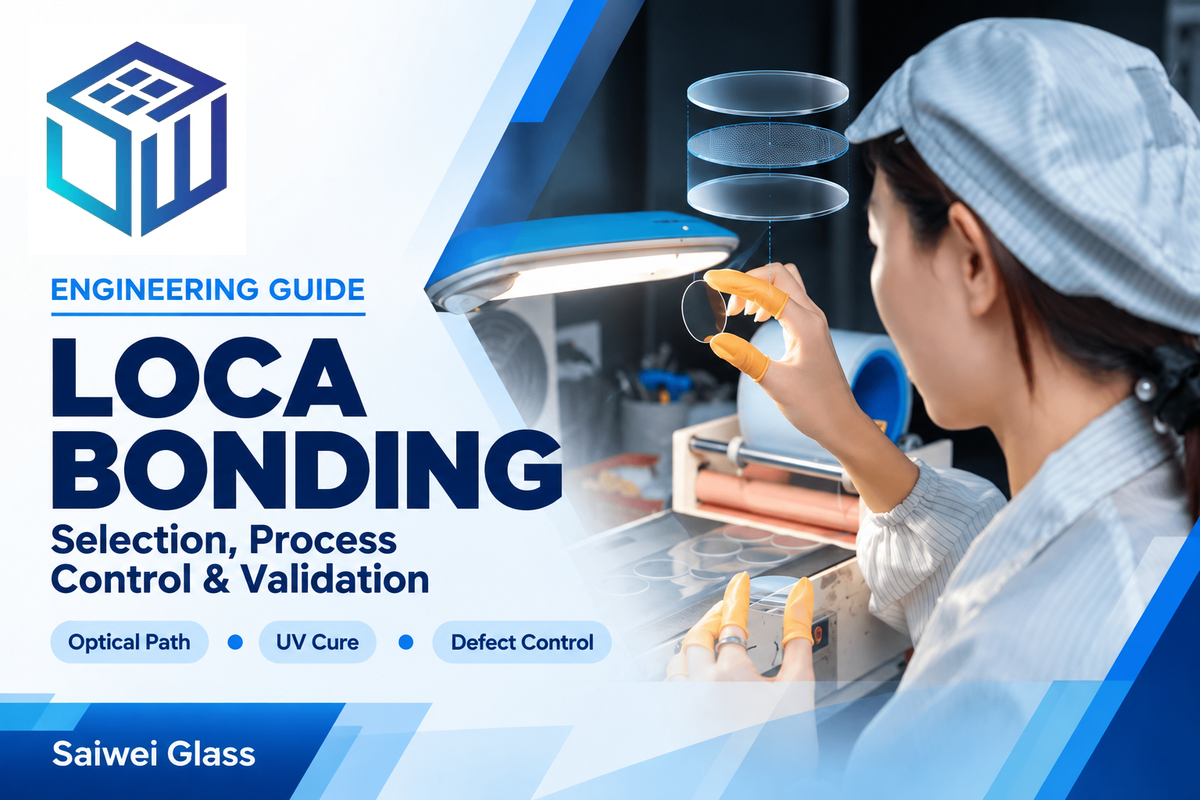
Display Bonding Engineering Guide
LOCA bonding is an optical assembly process for filling the gap between display layers with a transparent liquid adhesive; use this guide to compare adhesive options, define a repeatable UV-cure process, diagnose visible defects, and build a qualification plan for outdoor and marine display stacks.
Quick answer: LOCA bonding is a process that fills the space between rigid display layers with a liquid optically clear adhesive, then cures that adhesive, commonly with UV or UV/visible light. Replacing air with a transparent, index-matched layer can reduce internal reflections and parallax. Reliable results still depend on the adhesive chemistry, bond-line geometry, dispense control, cure energy, substrate compatibility, and validation of the finished stack.
That distinction is important. “Optically bonded” describes a construction method, not an overall performance evaluation. A bonded display may show better perceived contrast than an air-gap design, but its outdoor readability may still be limited due to the cover surface, coatings, panel luminance, viewing angle, ambient temperature and conditions, condensation and aging.
Among display bonding technologies, air gap bonding leaves a cavity while surface bonding fills it with an optically transparent medium. The bonding technique must protect optical clarity without introducing stress or uncontrolled variations.
For project context, Saiwei Glass fabricates custom cover glass, and its optical bonding service addresses stack assembly. This article focuses on engineering choices for liquid adhesive bonding, as opposed to repeating choices for either the commercial page or the fabrication page.
How LOCA bonding changes the optical path
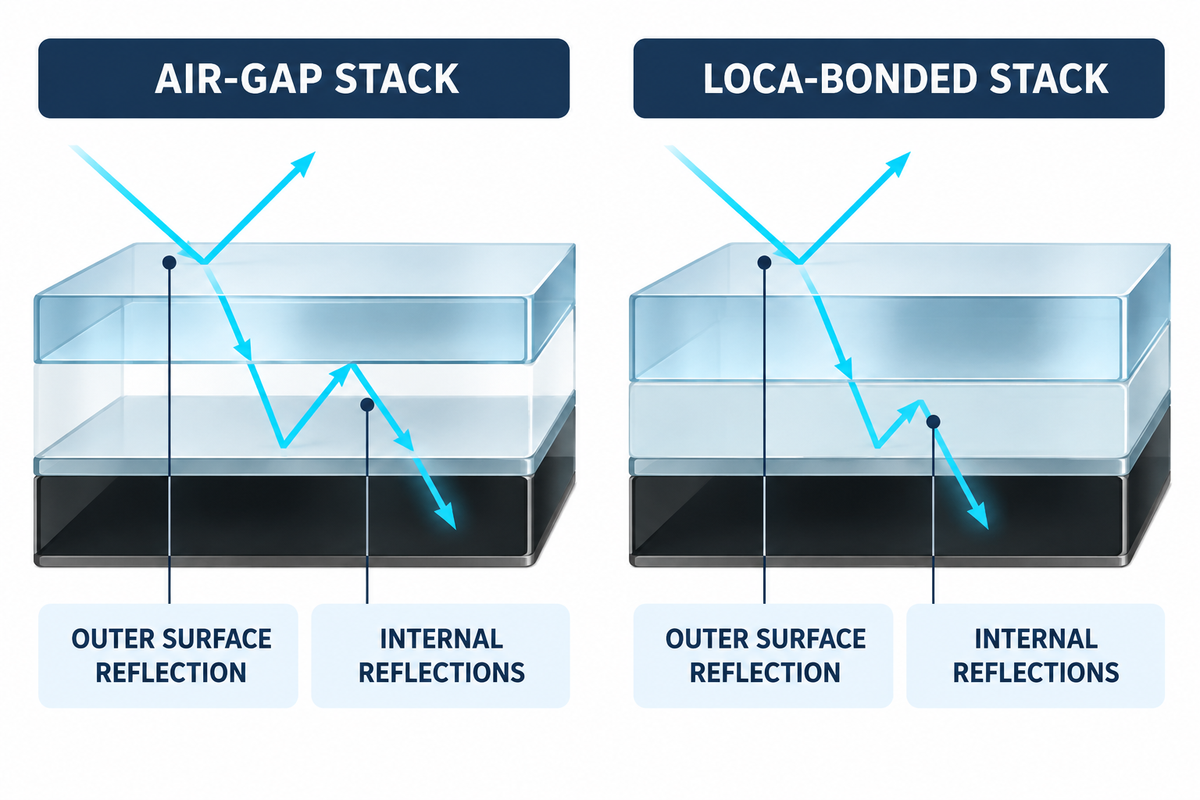
LOCA bonding is a way of replacing one or more glass-to-air interfaces with glass-to-adhesive interfaces. Because the refractive index of adhesive is closer to the optical materials compared to air, less light is reflected at the interfaces, and the image plane appears to be closer to the cover lens.
Air-gap stack
Cover lens → air → touch sensor/display. The large refractive-index step at each air boundary can create stronger internal reflections.
LOCA-bonded stack
Cover lens → cured transparent adhesive → touch sensor/display. The filled gap reduces abrupt index changes and supports a mechanically integrated stack.
The outer surface of the cover still is in contact with air, so there’s still surface reflection. Anti-reflective treatment, anti-glare texture, panel brightness, polarizer behavior, and the complete optical stack all influence the result. “Reduced Internal Reflection” must be treated as a mechanism, and “Sunlight Readable” as a system-level requirement that needs to be validated.
An LCD or touch display could use anti-glare or anti-reflective cover glass. Practical differences are explained in Saiwei’s AG, AR, and AF coating comparison. Those surface treatments solve a different part of the optical path than liquid optical clear adhesive.
Touch panels and display devices add electrical constraints to that optical path. In a capacitive touch stack, adhesive thickness and dielectric behavior can influence touch sensitivity even when the transparent optical layer looks uniform.
LOCA, OCA film, silicone gel, or an air gap?
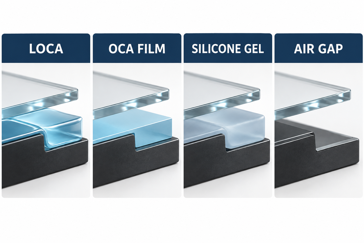
The best bonding method follows the display geometry, production route, cure access, rework strategy, and service environment. A materials-science overview from VIA Optronics likewise separates liquid, film, and silicone bonding routes by material behavior and application constraints. LOCA is attractive when a liquid can fill variable gaps or complex shapes, but a film or compliant gel can be easier to control in other assemblies.
In production language, LOCA adhesive, OCA bonding, air bonding, and hybrid bonding describe different material and assembly routes. A liquid optical clear adhesive can conform to a shaped gap, whereas a film-based OCA bonding process depends more on lamination geometry and particle control. Neither route is automatically the stronger bonding solution.
The type of bonding changes consumable format. OCA tape is a preformed adhesive tape, broadly described as double-sided adhesive, and LOCA is dispensed as a liquid. “OCA glue” and “LOCA glue” are common search terms, but they should not obscure the process distinction.
| Bonding type | Often suitable when | Process concern | Qualification focus |
|---|---|---|---|
| LOCA / liquid resin | Rigid layers, variable gaps, shaped cover lenses, or assemblies needing precise liquid fill | Dispense volume, overflow, entrapped air, cure access, shrinkage, shadowed regions | Bond-line uniformity, full cure, adhesion, yellowing, touch and optical change after aging |
| OCA film | Flat, consistent surfaces and a controlled lamination process | Particle control, alignment, lamination pressure, trapped air at features or steps | Lamination defects, edge stability, adhesion and environmental durability |
| Silicone gel / compliant optical resin | CTE mismatch, larger displays, vibration, or low-modulus stress relief | Material compatibility, pumping or edge containment, thickness control | Mechanical movement, optical stability, contamination and seal interaction |
| Air gap | Cost, serviceability, or optical bonding risk outweighs the benefit | Internal reflection, condensation space, mechanical separation | Readability, fogging, shock behavior and enclosure sealing |
Consider a curved cover lens over a rigid touch/display stack. A pre-cut film may bridge a local step or trap air at the transition, while a controlled liquid fill can conform to the geometry. However, a liquid process adds more design and control issues such as dam design, dispense pattern, closing speed, overflow and cure depth. LOCA favored geometries also favor process evidence.
Automotive and outdoor optical displays can give more weight to impact resistance and optical performance, but those finished-system properties can’t be attributed to adhesive alone.
The properties that define a usable LOCA process window
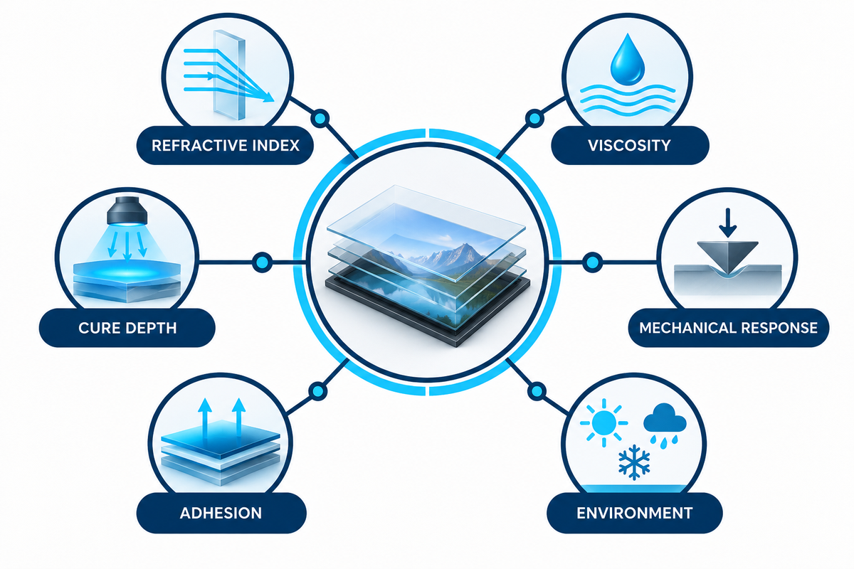
A usable LOCA isn’t the clearest material listed on the datasheet. Engineers need an overlapping window in which the liquid dispenses cleanly, wets the real substrates, cures throughout the intended thickness, limits stress, and retains optical and adhesive properties after environmental exposure.
| Property | Why it matters | Evidence to request |
|---|---|---|
| Transmission, haze, color and refractive index | Defines initial optical behavior and index matching | Test method, wavelength range, cured thickness, initial and aged results |
| Viscosity and flow | Affects dispense pattern, leveling, edge containment and bubble movement | Temperature-specific viscosity data and validated dispense window |
| Modulus, elongation and shrinkage | Influences stress transfer, mura risk and tolerance of thermal expansion mismatch | Cured-property data across the operating temperature range |
| Adhesion and compatibility | Controls delamination risk and interaction with glass, coatings, plastics, inks and seals | Results on the actual substrate and surface-treatment stack |
| UV/visible cure response | Links wavelength, irradiance, time and depth to conversion | Supplier cure curve, lamp spectrum, radiometer record and depth verification |
| Moisture, heat and UV aging | Drives yellowing, adhesion loss, edge lift and property drift | Combined and sequential exposure data with defined pass/fail criteria |
| Bonding strength after aging | Shows whether initial adhesion survives heat, humidity and mechanical loading | Failure mode plus retained adhesion on the actual touch screen or LCD display stack |
A NIST study of a different acrylate photopolymer system shows that differing formulations affect light penetration and critical energy demand. Those measurements aren’t LOCA process settings. They demonstrate that a given time setting can’t be transplanted to a different chemistry, lamp, thickness, or assembly.
A seven-step LOCA bonding process
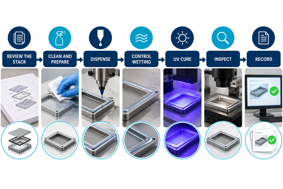
A stable process controls the stack prior to the dispensing of adhesive and verifies conversion after the lamp turns off. The NIST photopolymer study is a useful reminder that formulation changes affect light penetration and energy demand, so each step needs chemistry- and assembly-specific limits. The seven steps below form a practical baseline; each production line still needs material- and assembly-specific limits.
Industrial teams may call the uncured resin liquid glue, but repeatability requires it be treated as controlled material. Conditioning the material and observing the wet-front help reduce air bubbles before sealing.
- Review the stack: record substrates, coatings, inks, polarizers, active area, allowable edge zone, bond-line target and UV access.
- Clean and inspect surfaces using defined particle, residue and moisture controls as opposed to visual cleanliness.
- Design fixtures and edge controls to account for alignment, gap stops, dams, vents and capture overflow.
- Condition and dispense the adhesive controlling material lot, age, temperature, degassing, volume, needle path and pattern.
- Close the gap at a controlled speed and observe the wet-front to avoid trapping air around features.
- Inspect before cure for bubbles, incomplete wetting, contamination, edge overflow and nonuniform thickness while rework remains possible. Rework is possible.
- Cure and verify while recording the identity of the lamp, wavelength band, irradiance, exposure time, distance, fixture shadowing, and post cure checks.
Process rule: dispense volume, adhesive temperature, bond-line thickness, closing speed, wait time and delivered optical energy are linked variables. Changing one can move another defect, so record controlled trials instead of tuning by appearance.
The Defect-to-Control Matrix
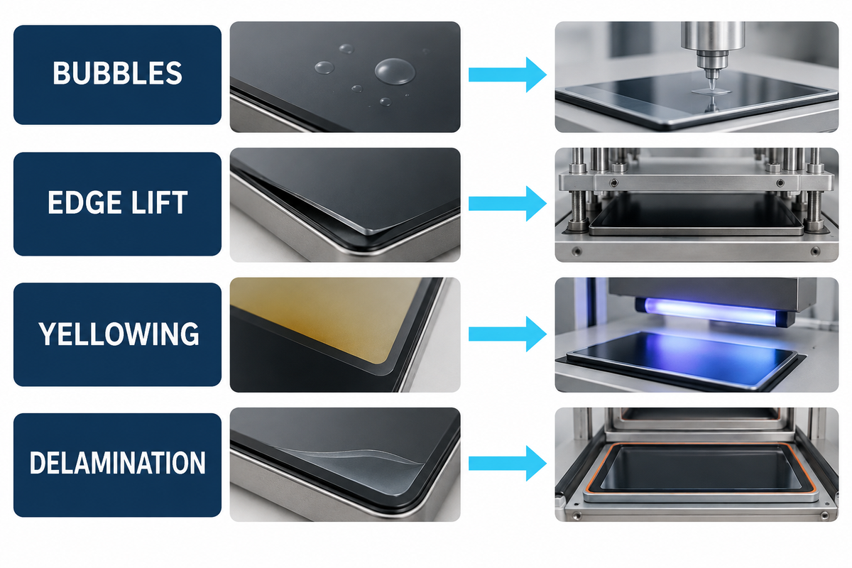
A visible defect is a symptom, not a root cause. Supplier cure guidance from Dymax shows why surface appearance alone cannot prove full conversion; defect review should combine location, timing, and process records. The fastest way to troubleshoot is to record the location of the defect, when it appears, and how it changes after cure or upon aging, before altering a process variable.
Curing the adhesive may freeze a temporary fill defect into a permanent optical defect. During one inspection pass, record glue overflow, edge wetting, and touch sensitivity. Thus, mechanical, optical and electrical symptoms will be correlated.
| Defect category | Possible cause families | Evidence to check first | Controlled response |
|---|---|---|---|
| Bubbles during fill | Entrained air, dispense path, wet-front collision, surface feature, high viscosity | Bubble location and time-stamped fill video; material conditioning record | Change one of path, speed, temperature or venting in a documented trial |
| Bubbles after cure/aging | Incomplete cure, outgassing, moisture, poor adhesion, thermal expansion | Cure-depth check, substrate lot, aging stage and cross-section | Separate cure, contamination and environmental hypotheses |
| Overflow or edge contamination | Excess volume, dam failure, gap variation, closing speed | Dispense mass/volume, fixture gap map and edge images | Correct the volume-gap relationship before changing chemistry |
| Mura or optical nonuniformity | Bond-line variation, cure shrinkage, mechanical stress, panel sensitivity | Thickness map, fixture force, cure sequence and powered-display image | Isolate geometric and stress effects with controlled samples |
| Edge lift/delamination | Contamination, weak substrate adhesion, moisture ingress, CTE stress | Failure surface, surface treatment, edge design and exposure history | Determine adhesive versus cohesive failure before selecting a remedy |
| Yellowing | UV/heat aging, chemistry, cure state or interacting materials | Color shift by region, spectral exposure, temperature and control coupon | Compare isolated and combined aging with the actual stack |
| Touch drift | Stack thickness, dielectric change, stress, moisture or controller calibration | Touch map before/after bonding and after each aging stage | Validate the bonded electrical stack, not only the adhesive |
| Surface haze or streaks | Residue, incompatible cleaner, partial wetting, coating interaction | Witness coupon, cleaning record and controlled-light inspection | Verify surface preparation before adjusting the curing process |
| Soft or tacky edge | Low UV light delivery, oxygen inhibition, shadowing, excessive thickness | Working-plane irradiance, edge geometry and depth-cure evidence | Correct spectral access and delivered energy before extending time |
Suppose bubbles are absent before cure, but appear near a printed border after thermal cycling. Increasing dispense volume isn’t likely to address the real issue. A better investigation compares cure access at the border, adhesion to the ink, local bond thickness, moisture history, and the failure surface. The timing and location of the defect narrow the cause family before the next controlled build.
UV cure: dose is not just exposure time
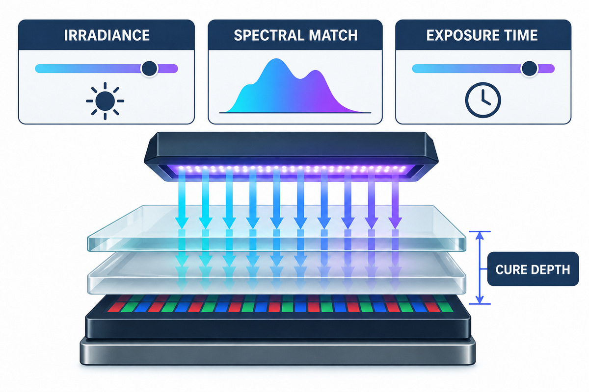
In the final analysis, exposure time is only meaningful in conjunction with the wavelength band and delivered irradiance at the adhesive. Lamp aging, distance, optics, fixture shadowing, adhesive absorption and bond depth can make two nominally equal time settings produce different cure states.
Dymax explains that a light-curable adhesive cures from the lamp-facing surface toward depth and that the interface against a substrate may be the last region to cure. Treat this as supplier process guidance and verify it for the selected LOCA. Dry surfaces aren’t adequate proof of full conversion.
Common mistake: extending time without measuring irradiance. Record irradiance at the working plane with a suitable radiometer, confirm that the lamp spectrum matches the photoinitiator, and include lamp age and fixture geometry in the batch record.
The Outdoor and Marine Validation Ladder
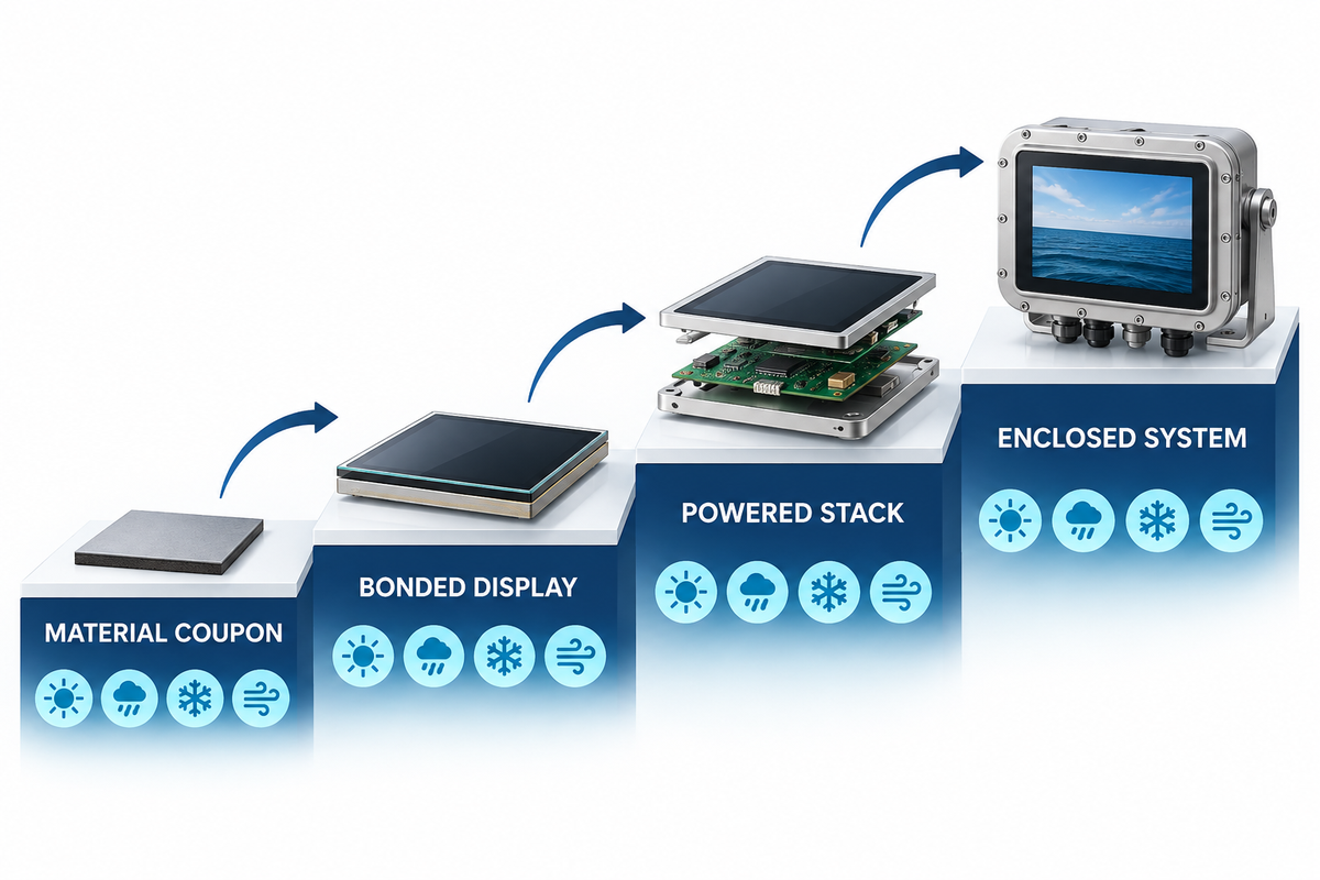
Outdoor and marine qualification should move from material screening to the bonded display and then to the enclosed system. Each level answers a different question; passing a coupon exposure cannot establish enclosure sealing, touch stability, vibration survival or sunlight readability. Passing one step won’t ensure the success of the next step.
1. Material screen
Compare cure, adhesion, color, transmission, haze, moisture response and compatibility on representative substrates.
2. Bonded-stack qualification
Measure optical uniformity, bubbles, edge condition, adhesion and touch behavior on the real layer stack.
3. System verification
Test the bonded stack inside the enclosure with seals, bezel loads, thermal paths, connectors and operating electronics.
4. Pilot and control plan
Confirm lot controls, lamp checks, dispense records, inspection limits and traceability on production-intent units.
ASTM G155-25 covers xenon-arc exposure involving light, heat and optional moisture, but its public significance-and-use text says the exposure is not intended to simulate saltwater deterioration. Marine programs therefore need separate corrosion and ingress logic. IEC 60068-2-11:2021 addresses salt mist, IEC 60068-2-6:2007 addresses sinusoidal vibration, and IEC 60068-2-78:2025 addresses steady-state damp heat. These are test methods; the project specification must still define severity, sequence, sample size, operation state and pass/fail limits. When exposure data will rank materials, the plan should also define concurrent controls, replicate count, and the basis for comparing equipment or laboratories; ASTM G155-25 places explicit limits on unvalidated cross-device comparisons. ASTM G151-26 further warns that laboratory exposure cannot reproduce every outdoor condition and that test hours cannot be converted directly into service years without material-specific correlation data.
For a helm display, a practical sequence might screen adhesive coupons first, then expose powered bonded stacks to temperature and humidity, then test the enclosed unit for vibration, water management and salt-related corrosion risks. Optical change, edge condition, touch maps and functional logs should be recorded at defined checkpoints. The correct sequence should be determined by the use case; it shouldn’t be determined from a material datasheet.
For commercial stack options and information to scope a complete application, see Saiwei Glass’s outdoor and marine display glass solutions. This guide intends to keep the engineering method; the application page owns supplier scope and project conversion.
What to put in a LOCA bonding specification or RFQ
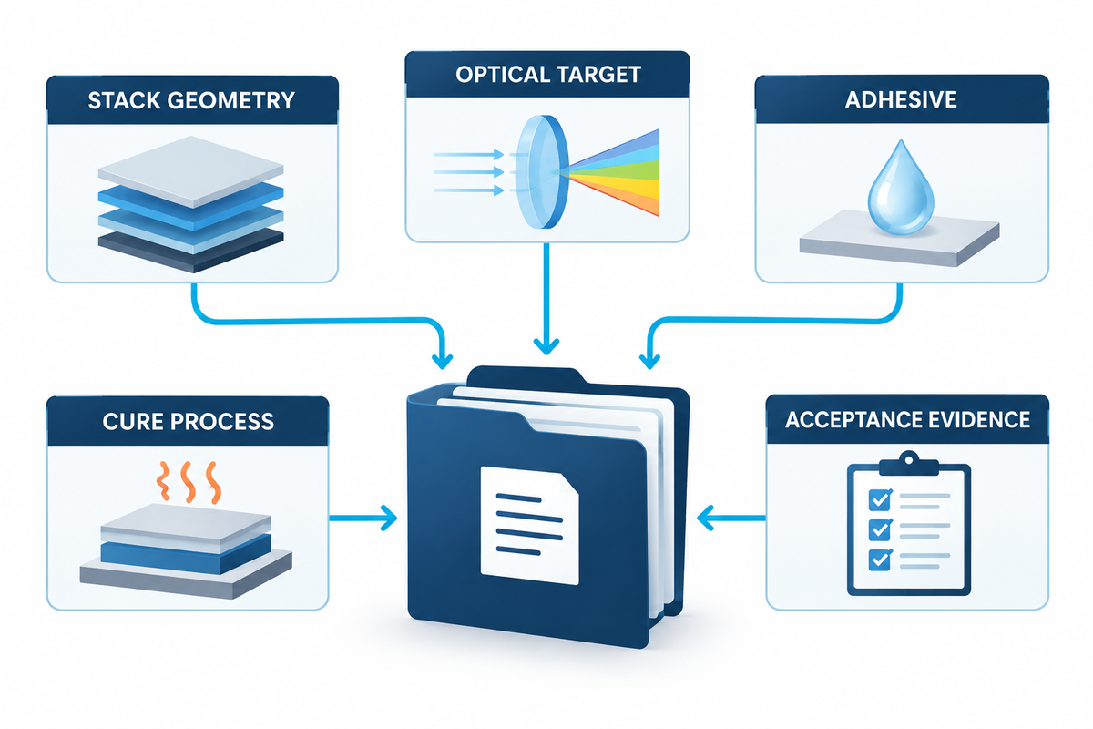
A useful LOCA RFQ describes the physical stack, environment, acceptance evidence and production volume—not only the display diagonal. RFQs that include the display size often make assumptions about the remaining display components, resulting in hidden assumptions for material and process selection.
The specification should identify the adhesive systems under consideration and state whether double-sided adhesive tape, liquid resin or another format is acceptable. It should also name the liquid crystal module and cover-lens interfaces that the supplier isn’t to change.
Pair the bonding brief with a controlled cover-lens drawing and a defined verification plan. Saiwei’s cover glass drawing checklist and cover glass testing guide cover inputs that remain outside the adhesive process itself.
- Cover lens, touch sensor and display drawings, materials, coatings, inks and active/view areas
- bonding line thickness and allowables, edge keep-out zones and cosmetic limits
- Operating/storage temperature, UV exposure, humidity, condensation, salt, vibration and shock conditions
- Optical targets with test methods: Transmission, haze, reflection, color shift, luminance/contrast
- Touch-performance requirements before and after environmental exposure
- Cure constraints, shadowed areas, allowed process temperature and rework
- Qualification sequence, sample count, inspection checkpoints and pass/fail criteria
- Annual volume, pilot quantity, traceability, change-control and required production records
Frequently asked questions
Is LOCA bonding the same as optical bonding?
LOCA bonding is one form of optical bonding. Optical bonding is the broader practice of filling the space between display layers with a transparent bonding material. LOCA specifically uses a liquid optically clear adhesive that’s dispensed into the assembly and cured. Other optical-bonding routes include optically clear adhesive film and compliant silicone-based systems.
Does LOCA automatically make a display sunlight readable?
No. LOCA can reduce reflection at internal air interfaces and may improve perceived contrast, but sunlight readability is a finished-system result. Cover-surface reflection, anti-reflective or anti-glare treatment, panel luminance, polarizers, viewing angle, optical uniformity, temperature and aging all contribute. Verify the powered stack under a defined illumination and measurement method.
What causes bubbles after UV curing?
Post-cure bubbles can originate from incomplete wetting, trapped air, outgassing, moisture, weak adhesion, excessive shrinkage or thermal-expansion stress. Location and timing are diagnostic: a bubble at a printed edge after aging suggests a different cause family from random bubbles visible during filling. Preserve samples and process records before changing viscosity or dispense volume.
Can LOCA be reworked?
Some LOCA assemblies can be reworked, but reworkability isn’t universal. It depends on the adhesive, substrates, coatings, panel sensitivity, bond area and removal method. A supplier statement that a process is reworkable doesn’t establish yield or damage risk for a particular stack. Validate removal and cleaning on sacrificial production-representative assemblies.
How do you choose between LOCA and OCA?
Start with geometry and manufacturing constraints. OCA film often suits flat, repeatable surfaces and controlled lamination. LOCA can accommodate variable gaps and shaped geometry but adds liquid-dispense, containment and cure controls. Compare particle risk, alignment, cure access, bond stress, rework, production volume and environmental qualification before selecting either route.
Which tests matter for a marine display?
A marine plan commonly considers UV, heat, humidity, condensation, water management, salt-related corrosion, vibration, shock, optical change, adhesion and touch performance. The exact severities and sequence must follow the installation. ASTM G155 alone is insufficient because its scope excludes saltwater deterioration; combine appropriate material, component and system methods with project-specific acceptance criteria.
Turn the use environment into a bonding specification
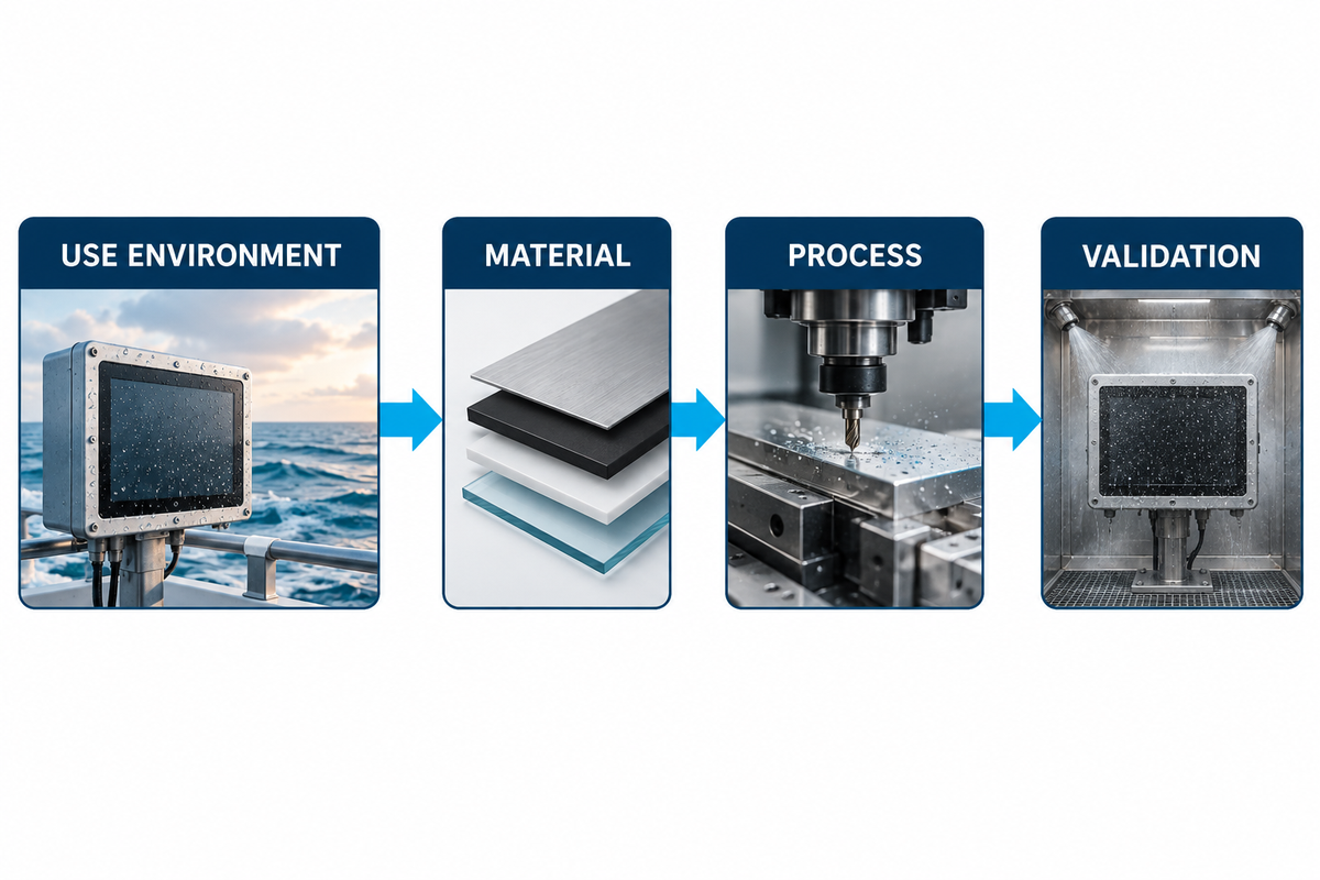
Share the layer drawings, optical targets, environmental profile and validation requirements. For application-specific stack options and supplier scope, continue to Saiwei Glass’s outdoor and marine display glass solutions page. Saiwei Glass can review the cover-glass and bonded-stack inputs without treating a material label as proof of finished-system performance.
References & Sources
- NIST: Influence of Fluorescent Dopants on Vat Photopolymerization
- ASTM G155-25 public significance and use
- IEC 60068-2-11:2021, salt mist
- IEC 60068-2-6:2007, sinusoidal vibration
- IEC 60068-2-78:2025, damp heat
- Dymax: Determining When Full Adhesive Cure Is Accomplished
- HumiSeal: Accelerated Weathering in LOCA Design
- VIA optronics: Optical Adhesives and Aging