Get in Touch with Saiweiglass


Transflective Display: A Complete Engineering and Buyer’s Guide

A transflective display is an LCD display designed to form an image with two light paths: It reflects ambient light in bright conditions and transmits light from a backlight when ambient light is insufficient. A transflective LCD display or TFT display may improve visibility in demanding lighting conditions, including direct sunlight and bright sunlight. That sounds like an automatic outdoor readability win. It isn’t. The relevant question is, does the selected panel, touch layer, bonding method, cover glass, and viewing geometry, provide enough contrast for the product’s true day and night cycle?
What a Transflective Display Actually Is
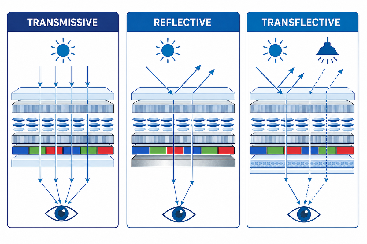
In a conventional transmissive LCD, the backlight provides the vast majority of usable light, while university-hosted transflective-display research shows how reflective and transmissive paths can coexist in one optical architecture. In a reflective LCD, incoming ambient light passes through the liquid crystal layer, gets reflected, and comes back to the viewer. A transflective LCD combines the two transmissive and reflective properties through a partially reflective layer or a pixel structure that separates reflective and transmissive areas.
This is relevant because sunlight readability describes an intended end state while “transflective” describes a means to an end. High-brightness transmissive LCDs, memory-in-pixel displays, reflective displays, and some emissive display solutions can also serve outdoor applications. The right architecture is dependent on the operating scenes, not the marketing label.
Reflective and transmissive displays are designed around different light paths. Therefore, transflective and transmissive designs should be compared under both bright environments and controlled low light.
The Two-Path Optical Model
- Ambient path: Daylight enters through the cover and display stack and reflects the image through the liquid-crystal.
- Backlight Path: Light originates behind the panel, traverses through the transmissive portion of the stack, and exits toward the viewer.
All elements from a polarizer to an adhesive to an air gap to glass can affect one or both of these paths.
How the Reflective and Transmissive Paths Share the Pixel
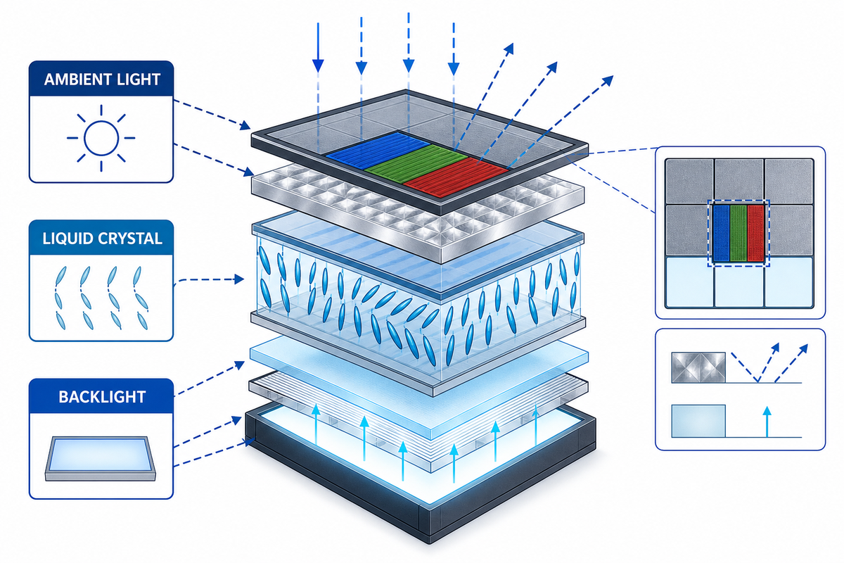
Transflectors don’t produce free light. They divert optical opportunity to reflection and transmission. In reflective mode, the pixels modulate with reflecting ambient light; in transmissive mode, the same display uses backlight. If a design prefers reflection, bright-day performance improves while backlight efficiency and color performance may degrade. If it prefers transmission, performance in low-light environments improves while less ambient light is returned to the viewer.
Different designs employ different concepts. Some use a semi-reflective layer, while others split the pixel into reflective and transmissive regions, or use different cell structures. Patent examples like US7969540 give possible structures, but a patent drawing should never be taken to mean a design discloses every production module.
The liquid-crystal mode, reflector texture, aperture ratio, color filters, backlight, and drive method all affect the result. That is why two modules sold as transflective may look different in bright light, overcast daylight, low light conditions, and direct sunlight.
Transflective vs Reflective vs Transmissive Displays
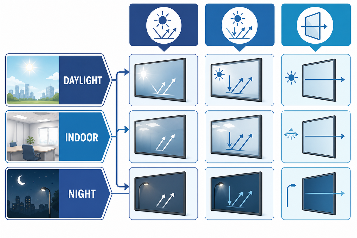
The fastest way to decide on an architecture is to consider where a product spends its time. U.S. Access Board display-readability research identifies viewing geometry, contrast, ambient conditions, and display technology as interacting variables. For example, an instrument that must remain readable in bright daylight while protecting battery life presents a different problem from an outdoor kiosk that can accept higher power consumption for saturated video. Comparison should distinguish optical architectures such as reflective LCD, transflective TFT, and transmissive TFT from panel or drive technologies such as IPS, OLEDs, and memory-in-pixel.
| Architecture | Bright ambient light | Dark conditions | Typical design tension |
|---|---|---|---|
| Reflective LCD | Uses ambient light | Needs front light or external light | Low power versus color and dark-scene capability |
| Transmissive LCD | Depends on backlight and reflection control | Strong, controllable illumination | Brightness, heat, and power versus daylight contrast |
| Transflective LCD | Can reuse ambient light | Uses a backlight | Two-path balance versus color, contrast, and complexity |
| Memory-in-pixel implementation | Designed for persistent outdoor content | Depends on product lighting design | Very low update power versus motion, color, and sourcing constraints |
Ambient-Light Duty-Cycle Matrix
Prior to requesting module samples, consider the percentage of time a product is used in direct sunlight, diffuse daylight, transitions between shade and sunlight, indoor and other lighted environments, and complete darkness. Then, consider color fidelity, motion, permitted backlight, thermal limits, and the range over which the module can be dimmed. This approach can define “outdoor use” for a product.
| Selection Type | Dominant condition | Architecture question | Validation focus |
|---|---|---|---|
| Direct-sun static data | High ambient light, limited motion | Can reflected light reduce backlight demand? | Ambient contrast at installed angles |
| Direct-sun color graphics | High ambient light, strong color requirement | Does a transflective tradeoff preserve required color? | Color and contrast in sun |
| Diffuse daylight | Broad sky illumination | Is reflective efficiency useful without a point source? | Uniformity and perceived washout |
| Rapid shade transitions | Changing ambient level | How will backlight control respond? | Transition time and control stability |
| Indoor operation | Moderate controlled light | Will the reflective structure reduce image quality? | Color, contrast, and viewing angle |
| Night operation | Low ambient light | Can the backlight dim far enough? | Black level, leakage, and minimum brightness |
| Battery-limited use | Restricted energy budget | Which duty cycle minimizes backlight energy? | Power across representative scenes |
| Polarized eyewear | Viewer uses polarized lenses | Does orientation create attenuation or blackout? | Required head and display angles |
| Wide observer zone | Multiple seated or standing positions | Which architecture retains usable contrast? | Off-axis luminance, color, and inversion |
For example, a product used for many hours in high ambient light may benefit from low power consumption and a reflective contribution. A module showing detail charts or video may benefit from purely transmissive displays with backlight. In this case, high power consumption needs to be considered with other thermal limits and power efficiency.
Read Optical Specifications as a System
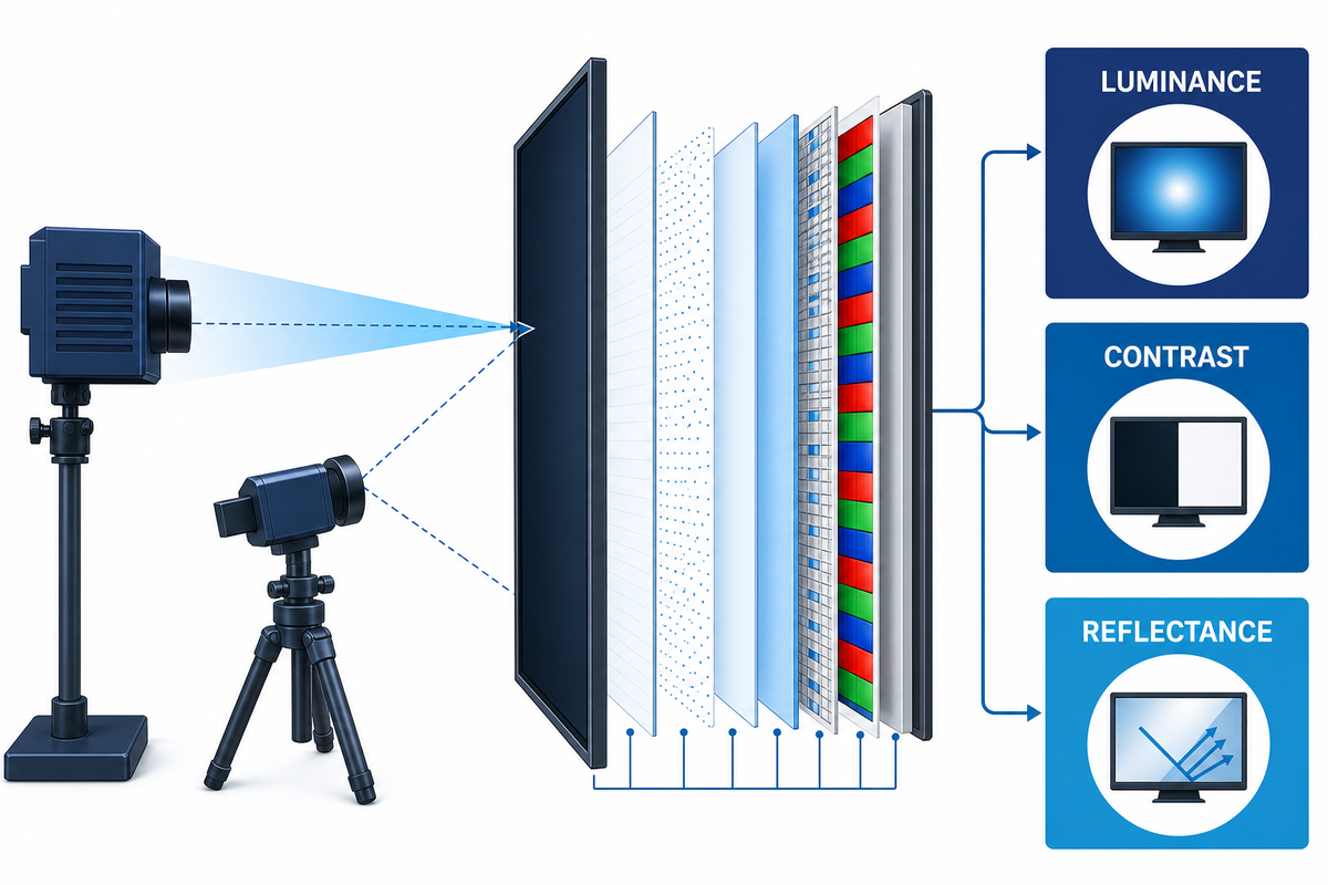
Luminance is only a line in the full optical specification. Other attributes that should be evaluated include reflectance, transmittance, ambient contrast, dark-room contrast, color gamut, viewing angle, response behavior, backlight power, dimming performance, and power curve. Each number needs its method, light source, and test state; otherwise claims of high contrast or excellent readability aren’t comparable.
- Reflectance: how much incident light is returned in a defined measurement direction.
- Transmittance: how efficiently backlight passes through the image-forming stack.
- Ambient contrast: the ratio between defined image states for a given illuminance and geometry.
- Viewing angle: how luminance, contrast, color, and inversion change away from the normal viewing direction.
- Power curve: how backlight behavior changes with ambient-light state, rather than at a single maximum value.
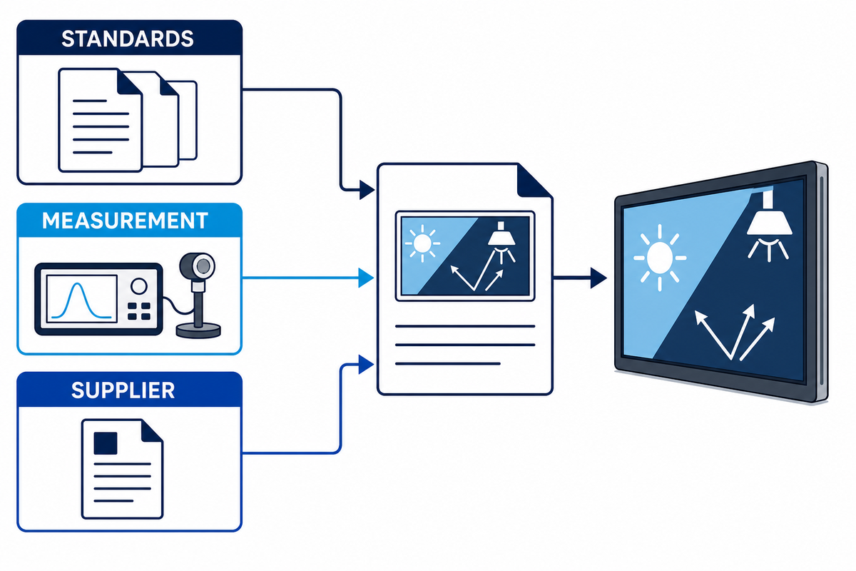
NIST display-reflection work shows that characterization of reflection relies on the nature and location of incident light. When assessing supplier data, consider the following: illuminance, source distribution, incident angle, measurement angle, state of content, polarization, and if the reading is done on a bare module or final stack.
Where Transflective LCDs Trade Image Quality for Efficiency
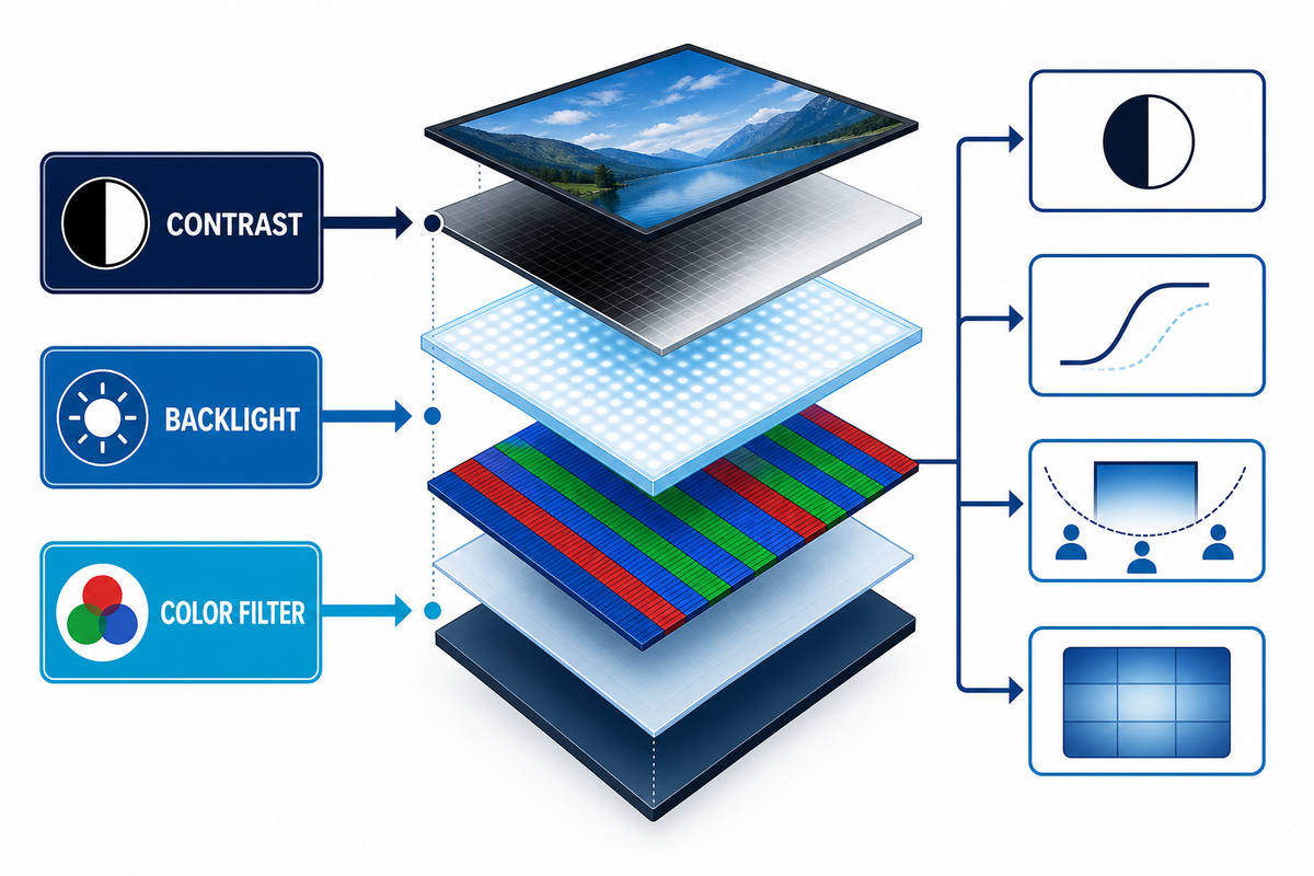
The reflective path can reduce dependence on a strong backlight; however, the architecture may introduce compromises in color saturation, contrast, aperture, uniformity, or viewing performance. Peer-reviewed transflective LCD research provides a quantified example of this brightness-and-contrast tradeoff. These trade-offs are design dependent and should be measured, not generalized from the term “transflective,” especially when high image quality matters across various lighting conditions.
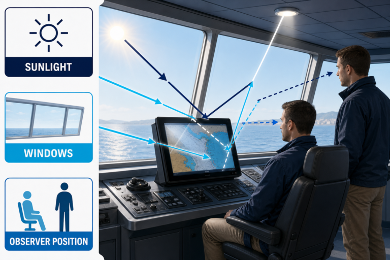
Mixed light can be revealing. A panel can look strong in direct sunlight and weak in diffuse indoor light. A panel may also perform well at head-on viewing angles but lose contrast at off-axis viewing angles. Also, polarized sunglasses can interact with a display polarizer making orientation part of the test plan.
Account for Touch, Bonding, and Cover Glass
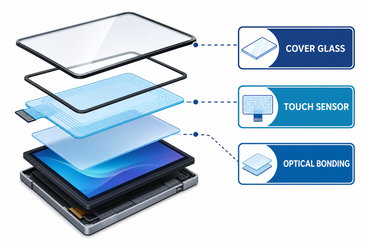
There are many considerations for a completed product, which go beyond the module. Examples are touch sensors and display modules, optically clear adhesive, air gaps, cover glasses, printed borders, anti-glare or AR coatings, fingerprint resistant coatings, and environmental seals. Each can alter the light returning to the user.
Complete-Stack Reflection Budget
Trace each optical path from the LCD to air and evaluate whether it’s bonded, spaced, coated, textured, laminated or contaminated. Evaluate each interface in both the backlight path and the ambient-reflection path. A treatment that preserves sharpness may still introduce sparkle, haze, or other artifacts, so evaluate those outcomes separately.
For a more detailed explanation of air gaps, consult Saiwei’s guide on optical bonding for sunlight-readable displays. For anti-reflective and anti-glare coatings, consult the dedicated anti-glare and anti-reflective glass guide.
- Operating-light scenes and observer positions
- Module model, revision, and optical mode
- Reflectance and transmittance methods
- Ambient contrast test geometry
- Luminance and dimming range
- Color and viewing-angle data
- Backlight power across operating states
- Touch sensor and bonding construction
- Cover-glass drawing and surface treatment
- Environmental exposure plan
- Production-intent samples and test reports
- Revision traceability and change notification
Saiwei Glass publicizes its capacities for custom cover glass manufacture, AG etching, and AR coating. Those services support the stack development efforts but aren’t a claim that cover glass determines the performance of transflective panels.
Validate a Transflective Display for Outdoor or Marine Use
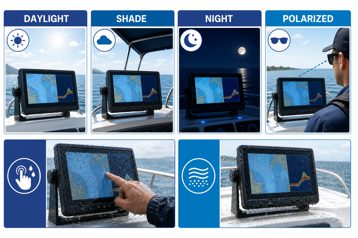
Validation should reproduce the optical viewing issue; enclosure, sealing, touch, and broader exposure qualification should follow the product-specific boundaries described in Saiwei’s outdoor and marine front-stack guide. A plan incorporating controlled measurements along with fixture level inspection and repeating critical verification after relevant exposure is useful. For applicable marine navigation and radiocommunication equipment, IEC 60945 provides standards context; the program must still define the edition, clauses, product category, and acceptance limits.
Outdoor Display Validation Card
- Identify scenes: Direct sun, diffuse sky, shade, cabin lights, darkness, and bright point reflections.
- Fix geometry: Source position, observer zone, display tilt and angle, polarization, and content representation.
- Record the stack: module, touch sensor, adhesive or air gap, cover glass, coatings, surface condition.
- Measure both modes: with the backlight reduced or off to evaluate reflective behavior, and with the backlight on at defined drive levels to evaluate transmissive behavior.
- Apply the following conditions for relevant exposure: temperature, humidity, UV, salt-laden atmosphere, abrasion and aggressive cleaning only where called for by the product risk assessment.
- Repeat optics: Compare pre- and post-condition readings, and perform fixture-level visual inspection.
Don’t convert chamber hours to field conditions in the absence of correlated data. A bare-panel reading won’t support a laminated product. And let’s be clear: a pretty sample doesn’t equal traceability. Record module revision, glass drawing, coating lot, adhesive, test equipment, method, date and the operator.
A Decision Framework for Module Selection and Supplier RFQs
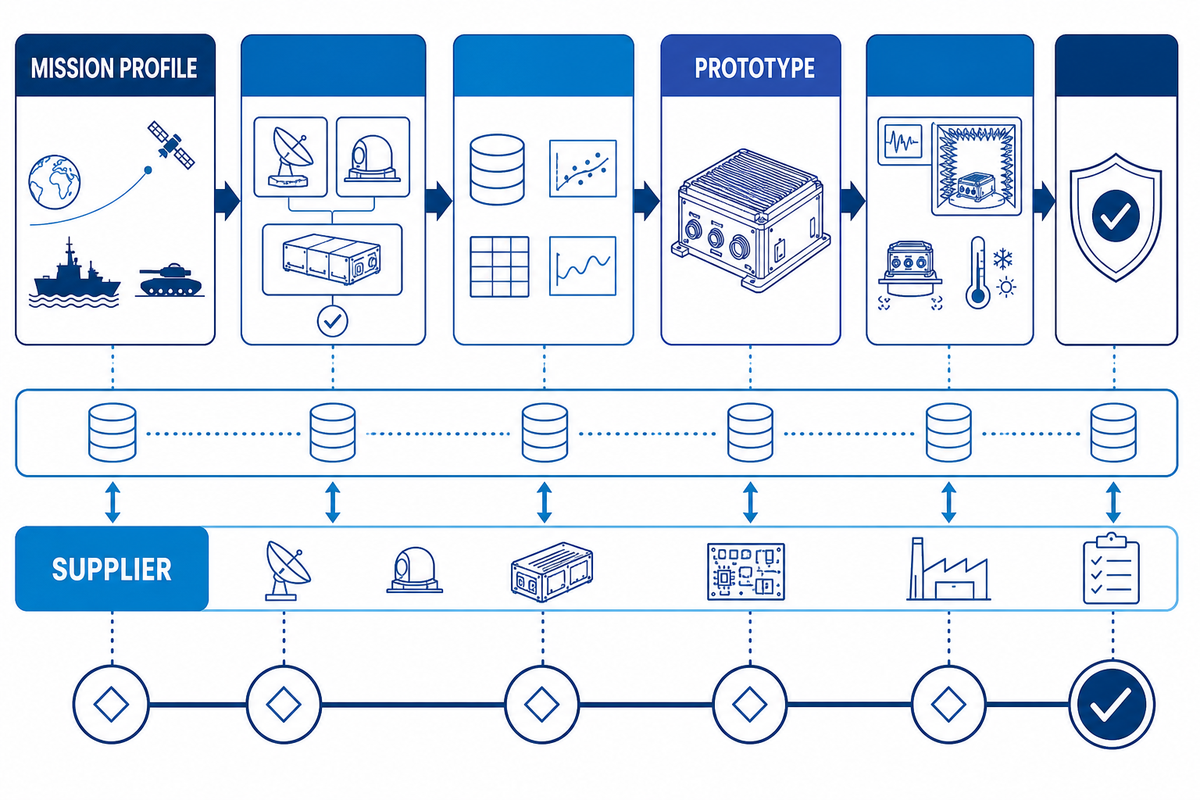
When issuing an RFQ for an LCD display module, operating conditions and evidence should come before your preferred display label. Whether the candidate is a standard transmissive LCD module or a custom transflective solution, follow this order:
- Define the ambient-light duty cycle and viewing zones. Consider the thermal limits and power budget. Determine the content and functionality, and specify day/night dimming.
- Depending on your system requirements, shortlist reflective, transflective, high-brightness transmissive, and memory-in-pixel solutions.
- State the cover and touch stack, including required surface treatments and whether interfaces are optically bonded or air-gapped.
- Outline the data, methods and samples required for determining reflectance, transmittance, contrast, luminance, color, viewing angle, response, and power.
- Representative prototypes need to be developed with an approved sample configuration, acceptance limits, change notification, and a documented validation record.
Size, resolution, interface, operating and storage temperatures, backlight control, touch technology, cover glass drawing, environmental plan, cosmetic requirements, sample quantity, test reports, expected lifecycle, and change control should also be included in the RFQ. Values should be defined for the project; average values from the internet shouldn’t be used to set limits.
| Evidence checkpoint | Why it matters | What to record |
|---|---|---|
| Operating scenes | Defines the real light-duty cycle | Direct sun, diffuse light, shade, indoor light, and darkness |
| Observer geometry | Controls reflected-light and viewing-angle results | Distance, height, tilt, and expected eye positions |
| Module identity | Prevents comparison across unlike revisions | Model, revision, optical mode, and firmware state |
| Optical method | Makes supplier values comparable | Illuminance, source, incidence, measurement angle, and content state |
| Touch and cover stack | Captures interfaces added after panel testing | Sensor, adhesive or air gap, glass, coating, and surface condition |
| Backlight control | Connects readability with heat and power | Drive level, dimming range, and representative operating states |
| Environmental exposure | Links durability testing to maintained optics | Applicable exposure, duration, sample state, and pre/post readings |
| Production sample | Binds approval to build intent | Drawing, lot, process, assembly, and approved comparison sample |
| Change notification | Protects the validated configuration | Controlled characteristics, notification trigger, and revalidation plan |
If a custom cover stack is required for exposure to the elements, analyze Saiwei’s outdoor and marine display glass capabilities and include the module stack, operating light profile, drawing and validation requirements.
Frequently Asked Questions
Is a transflective display always sunlight readable?
No. A transflective architecture can reuse ambient light. However, installed readability depends on other factors, including reflectance, contrast, polarizers, viewing geometry, content, touch layers, internal interfaces, cover glass reflections, and surface conditions. The module label is a good screening criterion. Final judgment must be made with the entire stack, represented in typical usage conditions and tested in the actual observer positions.
Is a transflective LCD better than a high-brightness display?
Neither architecture is universally better: a transflective LCD may decrease backlight demand in bright ambient light, while a high-brightness transmissive display may improve color and motion performance in another duty cycle. Consider differences in daylight hours, darkness, power, heat, dimming, color, viewing angles, content, and integration cost. Prioritize testing architectures when the tradeoff is likely to impact the business.
Does optical bonding improve a transflective display?
Optical bonding can reduce reflections from an internal air interface and improve mechanical integration, but the result still depends on the adhesive, touch sensor, polarizers, cover glass, assembly quality, and optical geometry. Bonding is just one option, not a certain solution. Validate the bonded production-intent stack and plan for process control, inspection, repair and long-term exposure.
Which specifications belong in a transflective-display RFQ?
A complete RFQ should state the operating-light profile and measurement geometry, then request reflectance, transmittance, luminance, dimming, ambient contrast, color, viewing angle, response, backlight power, temperature range, and the full touch-and-cover construction, with environmental exposures, production-intent sample evidence, revision traceability, change notification, the test method, sample configuration, module revision, and assumptions recorded for every reported value.
What should be tested for a marine transflective display?
Test representative day and night scenes, cross-polarization and viewing-angle interactions where applicable, gloved or wet operation, cleaning, and the environmental exposures required by the product program. Record production-intent stack performance before and after each test. Applicable standards and pass limits are determined by equipment category and approval plan.
Specify the Optical System, Then Validate the Mission
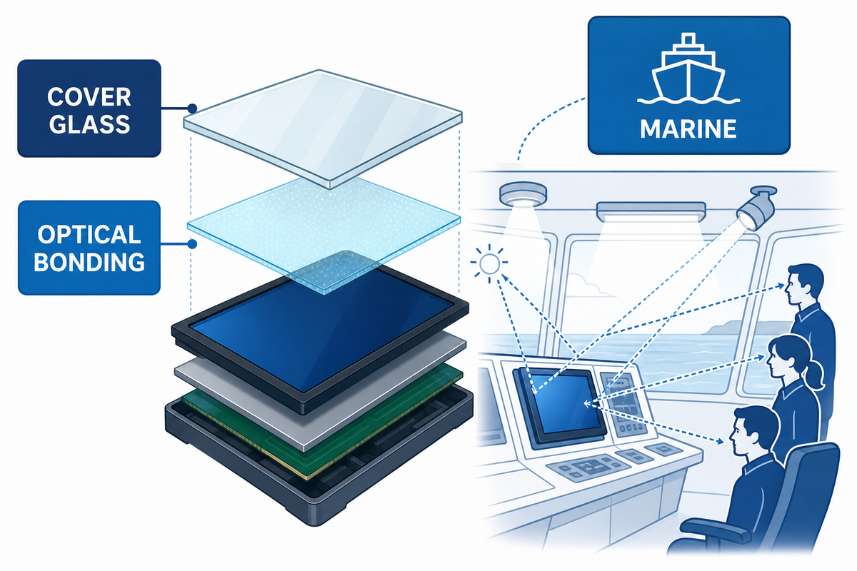
A transflective display combines ambient-light and backlight paths, but the installed system still carries trade-offs in reflection, transmittance, color, contrast, viewing behavior, power, and integration. The safest buying approach is to define the mission profile, analyze architecture families, and approve evidence tied to representative samples using a documented geometry such as the one emphasized in NIST daylight-readability research.
References & Sources
- Riverdi: Transmissive LCD vs Transflective LCD
- Focus LCDs: Transflective Displays
- Newhaven Display: Transmissive vs Reflective vs Transflective
- BOE: What Is a Transflective Display?
- NIST: Display Reflection Characterization
- IEC 60945 publication page
- US7969540: Transflective liquid crystal display example
Developing an Outdoor or Marine Display Stack?
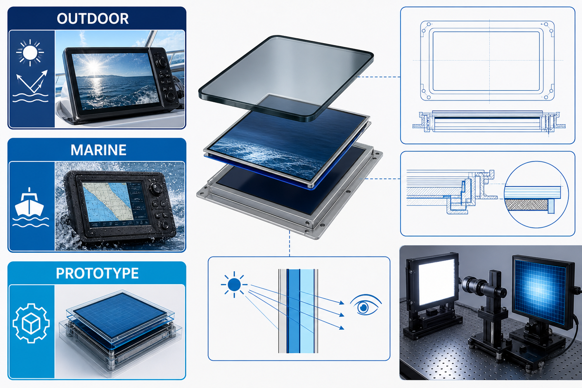
Bring your module specification, cover-glass drawing, light-duty profile, and validation needs to Saiwei Glass; NIST’s daylight-readability framework can help define the measurement conditions to include.