Get in Touch with Saiweiglass


Anti Glare vs Anti Reflective Glass: An Outdoor Display Test Guide


Anti glare vs anti reflective refers to two different ways of controlling visible reflections on display cover glass, and the better choice for an outdoor or marine display should be determined on a powered assembly in its actual lighting geometry. Anti-glare (AG) glass diffuses a sharp reflection, while anti-reflective (AR) glass reduces surface reflection and usually preserves finer image detail. AG is often utilized when multiple, wide-field, bright light sources move across the field. AR is more often utilized when image sharpness and contrast must be retained in a controlled viewing zone.
This document is a test and acceptance method for the engineers, product managers, and sourcing personnel. For the optical mechanisms and general comparison, see our industrial-display AG versus AR overview. In this document, the focus is narrower. How do you evaluate and approve cover glass for an outdoor kiosk, marine helm, deck display or other exposed control panel without relying on the “sunlight readable” label?
Short answer: test paired AG and AR samples on the actual display, map the brightest source and observer positions, score reflection control and image damage separately, then repeat the optical checks after the cleaning and environmental exposures that matter to the project.
Why Outdoor and Marine Installations Change the Answer

Displays in a laboratory have a stable observer, a predictable ceiling light, and controlled contamination. A helm or outdoor terminal doesn’t. The sun changes elevation and azimuth. An operator may stand or sit, clothing and other objects may be in the field of view. The display surface may collect spray, dust, sunscreen, and other contaminants.
These are important considerations because glare is geometric. A sharp specular reflection becomes severe when a bright source, glass surface, and observer are in line. AG texture spreads reflected energy over a larger angle and can soften a mirror image which may create a broad luminous wash. AR reduces surface reflection through an optical coating stack, but the outcome depends on wavelength, angle, substrate, coating design, and the rest of the display assembly.
In simpler terms, AG surfaces scatter light, so the observer sees a softer reflection as compared to a sharp, mirror-like reflection. This can reduce glare across a wider range of positions, but scatter can soften small content and increase eye strain during prolonged viewing. AR coatings use thin optical layers to reduce reflections at the surface; they do not filter blue light unless a separate function is designed into the coating stack.
Do not import rules from an eyeglass lens comparison. An anti-glare film, anti-glare screens, an anti-glare coating on display glass, and anti-reflective coatings on glasses can share similar vocabulary while employing different mechanisms, substrates, layers, viewing distance, and acceptance methods. This guide is about industrial cover glass and not a lens coating or consumer eyewear prescription.
The display stack and the cover glass are equally important. Air gaps, touch sensors, adhesives, display luminance, polarizers, and internal reflections affect the visible contrast. Optical bonding, for instance, is an approach for an internal interface, and cover-glass treatment is still relevant. Evaluate the complete powered assembly.
There are also mechanical changes resulting from the integration of glass features, edge treatments, openings, print borders, and treatment orientation. Saiwei offers CNC glass machining and chemical strengthening as adjacent glass fabrication processes on the following webpages that are coordinated with surface treatments.
Specification trap: “AG glass for outdoor use” and “AR coating for marine use” describe technologies, not acceptance criteria. A purchasing specification needs a sample, test geometry, measurement method, exposure sequence, and allowed change.
Keep the terminology tied to display glass
Key differences between anti-reflective and anti-glare start with the management of incoming light. An anti-reflection coating uses destructive interference between light waves in thin layers to cancel out reflected light over a designed range. It can increase light transmission, but no practical treatment can eliminate reflections at every wavelength and angle.
AG treatment employs a matte surface to redirect unwanted light. One way to accomplish glare diffusion is chemical etching, although the ultimate image quality depends on the complete surface specification and the display below it. A glossy screen is a good reference: it may appear clear in controlled lighting while showing greater mirror-like reflections when external light touches the surface.
The amount of light that returns to the observer is only part of the decision. When light hits a boundary, the surface can transmit, absorb, or redirect energy; when light reflects toward the eye, even a small bright region may block field content. Engineers and product designers therefore choose the right test scene before they choose the right treatment.
This language also justifies why “anti-glare and anti-reflective” isn’t repetitive. Anti-reflective and anti-glare treatments modify different optical components, and a combined screen cover may use both. Key differences are validated on the powered assembly, because screen use, pixel geometry, and touch layers can change the final result.
Anti-glare vs anti-reflective search results often display an anti-reflective coating for glasses. A person may ask for a pair of glasses comparing an anti-glare lens and/or ask whether to wear glasses. Those questions are beyond the scope of this industrial anti-reflective glass test method and require eyewear dispensing.
Light filtering isn’t the same as glare control for displays. A matte finish redirects light, while an AR design allows more light to pass through the interface by controlling light reflection near the top of the coating. The engineering goal is to reduce screen interference from ambient sources, without guaranteeing that the surface will reduce eye symptoms.
Well-designed treatments can help reduce eye strain caused by obscured content. User comfort is impacted by numerous factors including luminance, contrast, text size and viewing distance. The optical design should reduce screen reflections and manage light to reduce task interference; it shouldn’t be presented as a medical benefit.
Build a Light-Geometry Test Grid Before Comparing Samples
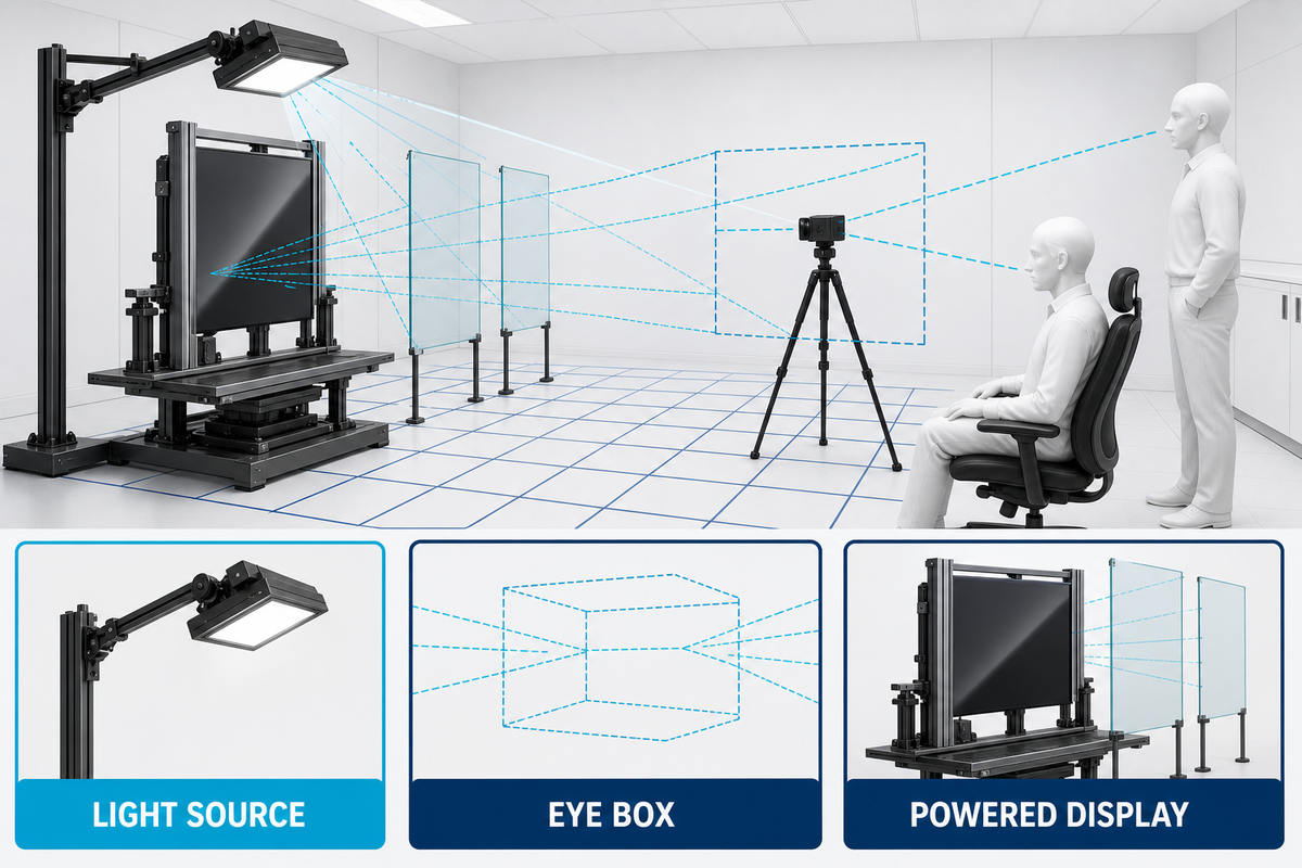
Start with the product as installed, not the coating data sheet. Mark every strong light source. For an outdoor or marine product, include the most difficult reflection path created by the sun’s position. For a display located on a bridge, include both seated and standing eye positions as well as windows and overhead lights; a peer-reviewed viewing-angle study illustrates why observer angle belongs in the test geometry.
Use the same image content, settings and conditions, and sample size for both displays. A user interface in a turned-off or dark state makes reflected sources obvious; then power the display so thin lines and small text reveal image-detail loss. Flat gray fields make nonuniformity easier to see.
For each critical cell, add a ray sketch. Show where incident light strikes the surface, where reflected light travels, and which eye point intercepts it. Sketches aren’t measurements. They keep the team from adjusting source and observer positions between the AG and AR trials.
Add polarized eyewear if it may be used by operators. The interaction of LCDs, touch sensors, cover glass, viewing angle, and polarized sunglasses may affect visibility. Treat eyewear as a controlled test condition; don’t assume the cover treatment by itself determines the outcome.
| Test cell | Source position | Observer position | Display content | Record |
|---|---|---|---|---|
| G1: direct-source alignment | Bright source placed at the predicted reflection angle | Primary operator eye point | Dark UI and alarm state | Sharp reflection, veiling wash, readable alarm details |
| G2: off-axis operation | Same source | Left, right, high, and low limits | Fine text and map lines | Contrast, color shift, line visibility |
| G3: broad ambient field | Diffuse sky or large luminous panel | Primary and secondary zones | Gray field and normal UI | Milky wash, nonuniformity, perceived black level |
| G4: moving-source sweep | Source swept through expected angles | Fixed operator eye point | Mixed bright/dark content | Worst angle and duration of interference |
Pictures of setups are valuable, but a picture isn’t a controlled observation or measurement. Pictures may be useful in documenting a particular state of setup, however, this depends on the context. A comparison picture may not be reproducible at incoming inspection without context.
Score Paired AG and AR Samples Without Hiding Trade-Offs
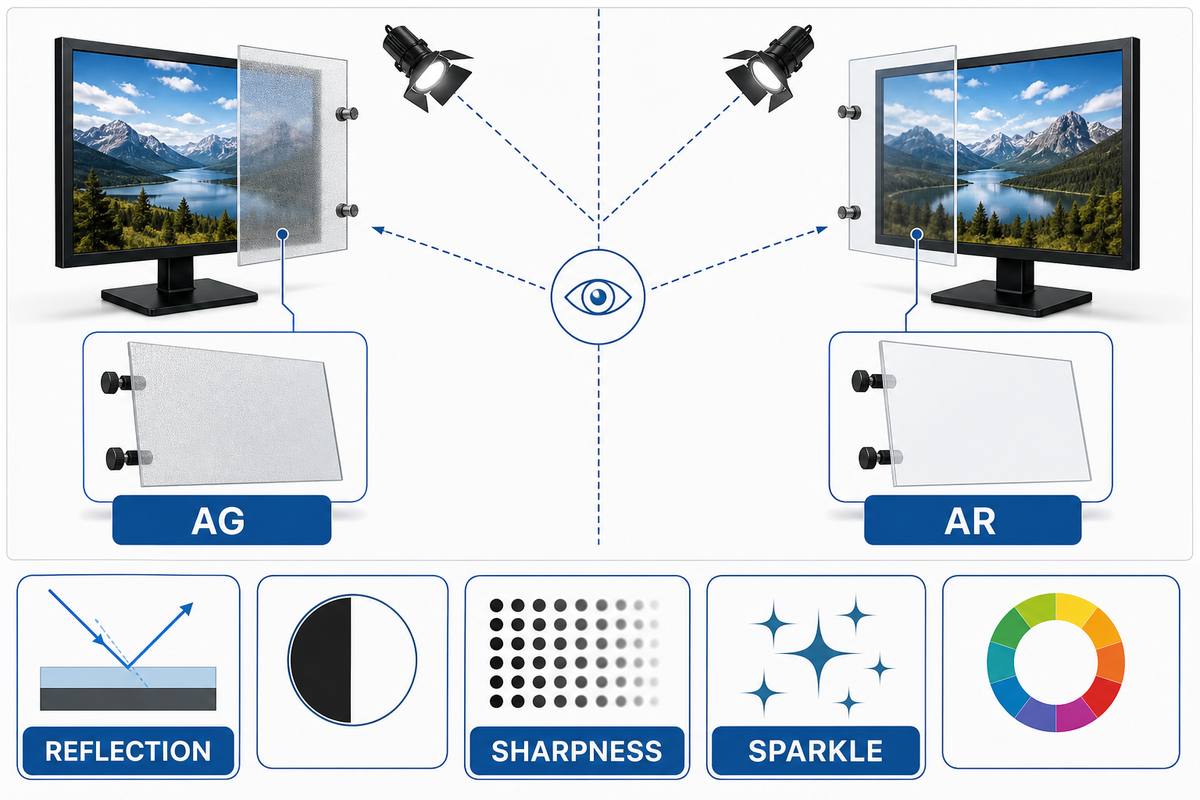
A single “readability” score conceals failure modes. Keep specular reflection, diffuse reflection, sharpness, sparkle, and cleanability as separate rows. ASTM D1003 provides a recognized framework for haze and luminous transmittance, but haze alone does not predict every display artifact. Repeatable sparkle measurement also requires controlled geometry and imaging conditions.
| Scorecard row | What to inspect | Why it stays separate | Acceptance approach |
|---|---|---|---|
| Specular reflection | Sharpness and intensity of reflected source images | A crisp reflection can obscure a small critical area | Compare at the worst mapped source angle |
| Diffuse wash | Broad lifting of dark areas under ambient light | A softened reflection may still reduce effective contrast | Use dark UI regions and a broad source |
| Fine-detail sharpness | Thin lines, small text, symbols, and edge clarity | Higher diffusion can reduce detail even when glare feels lower | Use the smallest safety-critical content |
| Sparkle | Grain-like modulation over pixel structure | It depends on surface structure and display pixel geometry | Lock distance, focus, display, and sample orientation |
| Color and uniformity | Tint, angle-dependent color, patchiness, coating defects | A low-reflection sample can still be visually unacceptable | Inspect neutral fields at defined angles |
| Cleanability | Residue, streaking, fingerprint visibility, surface change | Maintenance can change field performance | Use the approved cleaner, cloth, load, and cycle method |
Weight the rows by the product’s hazards and user tasks. For a navigation display, assign weight to line and symbol integrity according to the user task. A ticketing kiosk with moving sun reflections might give more weight to broad observer coverage. Keep raw row results, even if procurement needs a weighted total; otherwise, two samples with different risks might appear equivalent.
Where applicable, capture the measurement aperture, spectral range, incident angle, collection angle, calibration reference, and uncertainty. For visual scoring, capture viewing distance, evaluator instructions, rating scale, and decision rule. Compare blind to sample identity, if possible. These controls help result repeatability.
Just because there’s a small measured difference, doesn’t mean there’s a real world difference, and a product may not have an advantage just because of a small measured difference. Small measured differences could be affected by uncertainty in the measurement, repeated measurements, stray light from the instruments, or differences in the samples. When uncertainty prevents a defensible ranking, test more samples rather than forcing a ranked order.
Choose by Operating Scenario, Not by a Universal Ranking
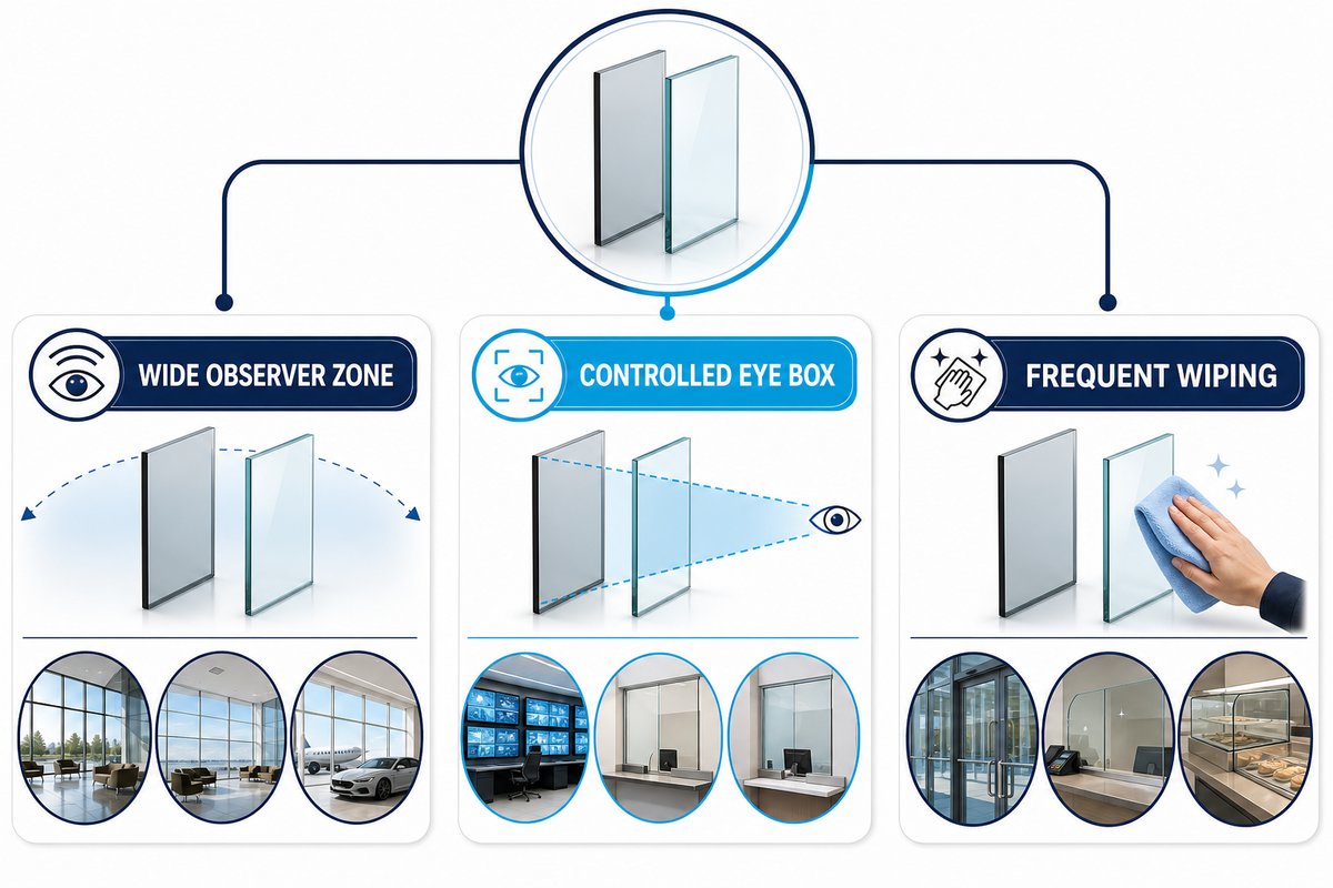
| Operating condition | Candidate to test first | Reason | Failure to watch |
|---|---|---|---|
| Wide observer zone with moving bright reflections | AG or a tuned AG/AR stack | Diffusion can reduce the distraction of a sharp reflected image | Veiling wash, sparkle, softened detail |
| Controlled eye box with small critical graphics | AR | Lower surface reflection can preserve fine detail | Residual reflection at off-design angles, color shift |
| Frequent wiping, salt residue, sunscreen, or public touch | Paired samples with the final top surface | Maintenance behavior may dominate the field result | Streaking, abrasion, residue, altered appearance |
| Optically bonded, high-resolution display | AR and low-sparkle AG variants | Internal reflection control does not resolve every front-surface trade-off | Pixel-coupled sparkle and assembly-specific contrast loss |
This matrix is to prioritize testing, not to dictate what to buy; the marine-display comparison likewise shows that sharp reflections and broad scattered wash are different operating problems. Sample both treatments when there’s a change in the operating geometry during the day, if safety-critical content is small, and/or if there’s frequent surface cleaning. A hybrid stack may also be appropriate, but every additional surface function—such as anti-fingerprint behavior—must be represented in the production-intent sample.
Run an Exposure-to-Optics Loop
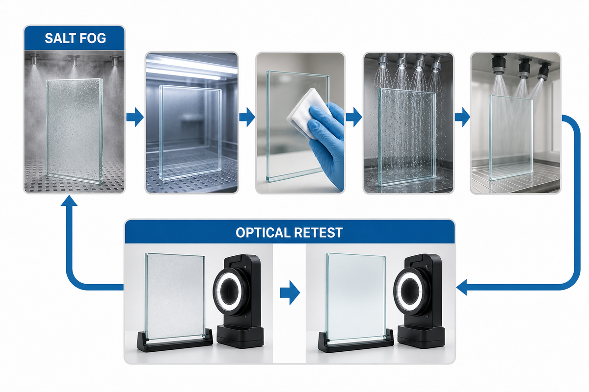
Environmental testing becomes useful when it answers a product question. ISO 9211-3 organizes environmental durability requirements for optical coatings, while salt-fog methods provide controlled exposure conditions. Neither justifies translating chamber hours directly into years of marine service. Choose exposures from the real use and maintenance profile, then compare optical performance before and after.
- Establish a baseline. Photograph and measure the clean, unexposed sample in locked geometry. Describe appearance, and haze or transmitted light if applicable, reflection behavior if applicable, sparkle, and visible fine detail.
- Create a defined exposure condition. Use an approved project cleaning, conditioning, or exposure method.
- Prior to examining the optical surface, allow for a period of time for equilibrium. Define the cleaning and recovery process. Evaluate the surface, and if residue or moisture is present, do not assume it is coating damage.
- Repeat the same optical test. Describe the change, if any, not just a pass/fail.
- Monitor interactions. When a product is subjected to sequential stresses, assess the relevant sequence by testing on multiple samples or by using a controlled combined plan. Don’t rely on isolated tests to prove interactions.
Decision rule: durability is not complete when the coating remains attached. The surface must still meet the project’s optical and cosmetic requirements after the defined exposure and approved cleaning process.
Build a Sample-to-Production Acceptance Pack
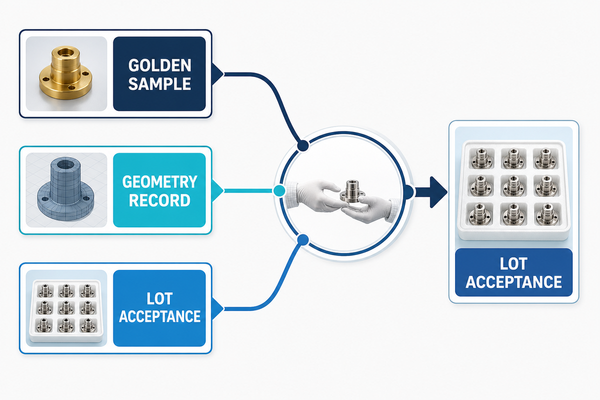
A sample can become a poor production specification if its identity and test conditions are lost. Bind the optical decision to a golden sample and controlled record. Avoid using generic tolerances from unrelated displays and standards. Set project limits from verified samples, the instrument method, and the risk of the user task.
| Acceptance pack type | Minimum record | Prevents |
|---|---|---|
| Golden sample identity | Unique ID, revision, supplier, substrate, thickness, treatment side, coating stack, date | Approving an untraceable prototype |
| Display-stack definition | Display model, touch stack, bonding material, air gaps, drive settings | Testing glass independently of the final assembly |
| Geometry record | Drawings/photos, source type and position, eye points, distances, angles | A nonrepeatable showroom comparison |
| Optical scorecard | Separate results for reflection, wash, sharpness, sparkle, color, defects | One average score hiding a critical failure |
| Surface-care method | Cleaner, concentration, cloth, force or apparatus, cycle count, drying method | Uncontrolled cleaning damage and disputed results |
| Change control | Variables requiring notification and requalification | Silent changes to texture, chemistry, layer stack, or process |
| Lot acceptance | Sampling rule, instrument settings, cosmetic zones, limits, disposition route | A lab approval that cannot govern production |
| Requalification trigger | Named material, process, equipment, supplier, and site changes that reopen approval | Treating an earlier approval as a permanent quality guarantee |
Common mistakes are easy to spot in this record: specifying haze without sparkle, approving an unpowered sample, omitting the treatment side, using a clean-room wipe that operators will never use, and accepting a vendor’s “equivalent” process without requalification. Treat any change to substrate, texture, coating chemistry, layer stack, cure, cleaning recommendation or critical supplier as a record trigger.
Acceptance sampling provides information about a bounded question about a current lot; it isn’t long-term process control. Determine the sample size and acceptance criteria with the relevant quality team, and monitor production trends separately. This distinction prevents a golden sample or an accepted lot from being treated as proof that future output cannot drift.
Relative sample preference is not proof of regulatory or equipment compliance. A marine navigation display may be subject to product specific standards and test result requirements that aren’t applicable to a general outdoor terminal. Identify the equipment standard first, obtain the applicable full text, and keep its mandatory tests separate from this surface-treatment comparison.
Saiwei Glass creates custom cover-glass solutions for outdoor and marine applications. State your display stack, mechanical drawing, viewing geometry, exposure profile, and target scorecard when requesting samples. This information makes the first sample round more useful than a request for “the best anti-glare glass.”
Discuss Your Outdoor Display Glass
Frequently Asked Questions
Is anti-glare the same as anti-reflective?
No. Anti-glare surfaces diffuse reflections, while anti-reflective coatings reduce reflection through optical interference. Because the mechanisms differ, they can produce different effects on sharpness, sparkle, color, cleaning, and long-term surface condition, so the correct choice depends on the installed display and its light geometry.
Which is better for direct sunlight?
There is no universal winner for direct sunlight. The choice depends on the sun-reflection path, observer zone, display luminance and stack, content detail, and surface condition. Compare paired AG and AR samples in the worst installed geometry. Repeat the comparison at the edge of the operator eye box. Include a contaminated or recently cleaned condition.
Does lower haze mean better outdoor readability?
Haze alone is not a sufficient measure of outdoor readability. Specular reflection, diffuse wash, display contrast, viewing angle, sparkle, and contamination can also limit what an operator sees. Treat haze as one row in a broader scorecard and compare it with the powered display in the intended light geometry.
Can AG and AR be combined?
Yes. An anti-reflective coating stack can be integrated with a tuned anti-glare surface texture, but the combination must be assessed as a complete production-intent sample. Check reflection control together with sharpness, sparkle, color, cleaning, touch behavior, and the environmental exposures specified for the finished display assembly.
What should a supplier receive before making samples?
Provide the supplier with the cover-glass drawing, substrate and thickness requirements, treatment side, touch and display stacks, bonding method, observer and light geometry, exposure environment, approved cleaning method, cosmetic zones, acceptance scorecard, required sample conditions, and the measurement records that must accompany quotation and production release.
References & Sources
- ISO 9211-3:2024, Optical coatings, environmental durability
- ISO 9227, Corrosion tests in artificial atmospheres
- ASTM D1003, Haze and luminous transmittance of transparent plastics
- Corning, What is a surface treatment?
- Radiant Vision Systems, repeatable measurement of sparkle in anti-glare displays
- Peer-reviewed study of display viewing-angle effects