Get in Touch with Saiweiglass


Choosing cover glass flatness tolerance for bonding and seals

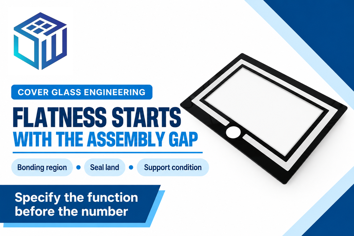
Cover glass flatness tolerance limits how far a surface can deviate from a plane over a defined area. Take a limit from the assembly’s functional gap, then specify how the finished glass will be measured. A thickness tolerance or optical appearance check can’t determine that number. The same cover can require different controls across the viewing area and the perimeter seal.
Cover glass flatness tolerance is a surface-form requirement. Set it from the bonding or sealing gap and an agreed inspection condition. Treat installed tilt, thickness variation and measurement uncertainty separately.
Quick Specs: what the requirement needs
- Flatness is a total zone between parallel planes, not a plus-or-minus position limit.
- Define the controlled face and functional area before choosing a number.
- Measure the finished part under agreed support, with the evaluation method stated.
- Use material-specific bonding or compression limits; geometric fit alone doesn’t qualify a seal.
Choose a cover glass flatness tolerance from the assembly
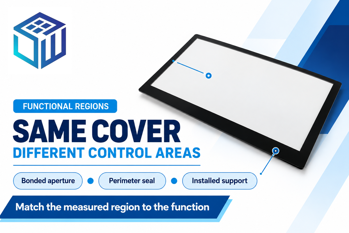
A reasonable requirement keeps the local bonding gap or sealing compression within the application’s qualified range. Begin with that range and the mating surface, and then allocate the allowed geometric variation. A purchasing spec that begins with an unexplained micrometer value leaves the custom cover glass manufacturer and the incoming inspection guessing about the purpose.
What is a reasonable flatness tolerance?
A reasonable flatness tolerance is the least restrictive surface-form limit that supports the requirement of the assembly under its specified conditions. The number depends on the controlled area, cover stiffness, and the mounting and bonding methods. A perimeter gasket, for example, requires a controlled gap around the sealing land; a full-area optical bond requires a suitable gap across the region that’s to be bonded.
ASME Y14.5 supplies the language for dimensional and geometric requirements. The functional choice remains an engineering decision. Record the intended cover support and mounting angle before translating an assembly allowance into a drawing callout.
For an industrial touch-screen cover, a small apparent improvement in free-state flatness may provide little value if the housing still tilts the cover. Compare the assembled gap map to the surface map before tightening the purchase limit.
Flatness, bow, and thickness variation are different
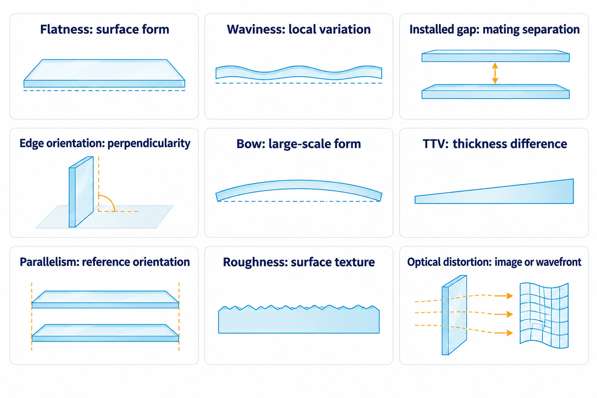
Flatness describes one surface’s form; thickness variation compares the separation of two surfaces. Bow describes larger-scale surface form, while waviness and roughness describe surface features at a smaller scale. A precise report gives the quantity and evaluation area. Two apparently similar numbers can describe different properties of the same glass.
| Quantity | What it describes | What to keep separate |
|---|---|---|
| Surface flatness | Form within two parallel bounding planes | Installed height and tilt |
| Local waviness | Shorter-scale surface variation within a defined region | Full-part bow |
| Installed gap | Separation of mating surfaces in their assembly positions | Free-state form of either part |
| Edge orientation | Whether an edge is perpendicular to the specified reference | Form of the broad glass face |
| Overall bow | Large-scale departure using a stated evaluation convention | Local waviness at the sealing land |
| Total thickness variation | Difference between maximum and minimum measured thickness | Flatness of either face |
| Parallelism | Orientation relative to a specified reference | A standalone flatness requirement |
| Surface roughness, Ra | Texture under specified filtering and sampling | Full-part surface form |
| Optical distortion | Image or wavefront behavior through or from the part | A direct geometric acceptance value |
Vijay Srinivasan, Craig Shakarji and Ed Morse in their fitting study distinguish representative sampling from whether fitted geometry matches the product specification. State the fitting criteria and units. A least-squares reference plane and minimum zone evaluation shouldn’t be treated interchangeably.
The thickness of the glass also affects how carefully support must be defined. Neither a smooth finish nor uniform thickness indicates that a thin cover is flat in its installed condition.
Match flatness to bonding and sealing
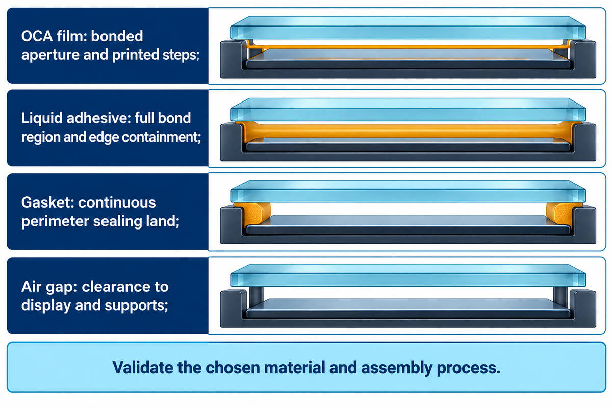
Choose the controlled region from the way the cover meets the assembly. A full-area optical bond, a perimeter gasket and an air gap impose different constraints. The 2023 optical-bonding process paper’s public abstract identifies adhesive type, display stack and requirements as reasons process steps differ.
| Assembly route | Control region | Decision before setting flatness | Validation to retain |
|---|---|---|---|
| OCA film laminate | Bonded aperture and printed steps | Match local gap to the chosen film and lamination process | Contact, bubble removal and optical appearance |
| Liquid optical adhesive | Full bond region and edge containment | Define the permitted cured bondline and dispensing conditions | Fill, cure and adhesion across the region |
| Compressible gasket | Continuous perimeter sealing land | Keep minimum and maximum gap within the qualified compression window | Closing force, aging and leakage performance |
| Air-gap display | Closest approach to the display and supports | Maintain clearance under the specified assembly conditions | Contact avoidance and acceptable display appearance |
Film isn’t automatically rigid. 3M’s September 2026 CEF38XX data sheet describes a soft, UV-curable optically clear film that conforms to ink steps. Its CEF3804 nominal film thickness is 100 μm, a product value rather than a permissible glass bow. For liquid material, use the liquid optical bonding process to define the bondline before assigning geometry limits.
According to Rogers’ enclosure-seal guidance, the general guideline gives 25-35% compression as a starting value and also takes compression force into account. A chosen gasket still needs application qualification; an increase in closure force can deform a thin enclosure.
Work through a local gap allowance
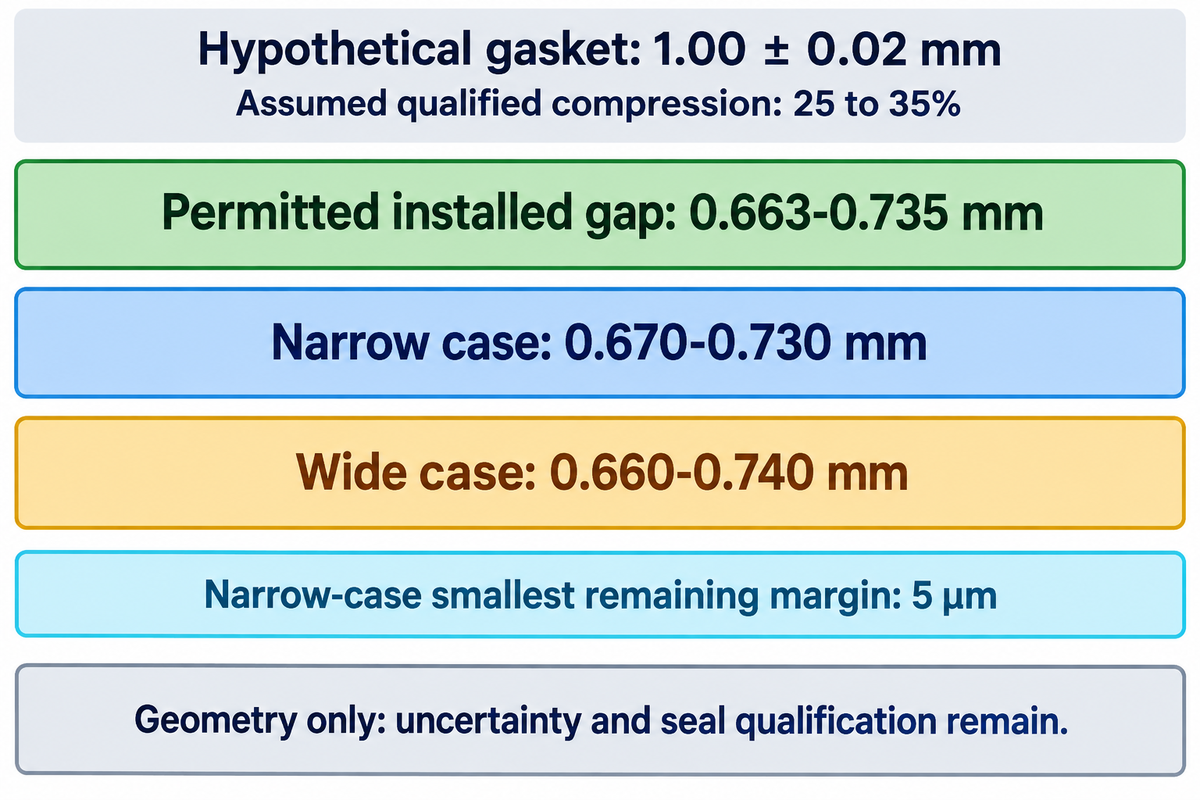
A budget for the gap must include the installed relationship between the two mating surfaces. Intrinsic flatness alone doesn’t define this positioning. A worked-example comparison and chart show how variation in gasket thickness reduces the available geometric window. The example presented here is a hypothetical design calculation to establish the gap, not a measured Saiwei capability or a sealing-performance test.
Assumptions: It’s assumed that the application qualified 25 to 35% compression for the chosen material. The effective uncompressed gasket thickness is 1.00 ± 0.02 mm, with no additional adhesive layer. The installed nominal gap is 0.700 mm. All dimensions are for the same functional sealing land.
At the thickest gasket condition, the minimum gap required to not exceed 35% compression is 1.02 × (1 – 0.35) = 0.663 mm. At the thinnest gasket condition, achieving at least 25% compression requires a gap no greater than 0.98 × (1 – 0.25) = 0.735 mm.
| Total installed gap variation | Resulting local gap | Comparison with 0.663–0.735 mm |
|---|---|---|
| 0.700 ± 0.030 mm | 0.670–0.730 mm | Inside; remaining margins 0.007 mm (7 μm) and 0.005 mm (5 μm) |
| 0.700 ± 0.040 mm | 0.660–0.740 mm | Outside at both ends |
The ideal window is 0.072 mm wide. For the wider-variation case, the lower end misses by 0.003 mm and the upper end misses by 0.005 mm.
The ±0.030 mm term is an assumed bound on total installed gap variation. It isn’t a flatness callout divided by two. Establish that bound from the mating maps, assembly position, and support conditions without counting the same variation twice. Add any separate adhesive or coating to the thickness stack and housing-depth calculation.
The smallest remaining margin is only 5 μm. ISO 14253-1:2017 addresses uncertainty in conformity decisions near specification limits. Thus this ideal calculation does not prove that inspection resolves acceptance. Agree the uncertainty and decision rule before spending the margin; force, temperature, aging and leakage remain separate qualification questions.
Measure the finished glass without flattening it
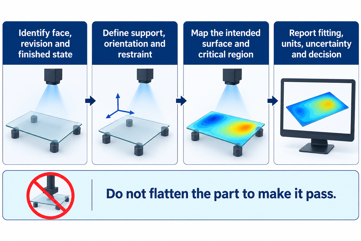
Measure the specified surface under a repeatable support condition that represents the drawing requirement. Pressing a compliant cover against a reference plate can change the shape that’s being inspected. Gravity, mechanical clamping and chucking are a few of the sources of deformation described in NIST’s 2010 thin-optics research.
How do you measure flatness?
Measure surface heights across the agreed area, then evaluate those points using the specified flatness criterion. The method must resolve the required error without changing the part’s shape or mixing its front and back surfaces. Use the same support, orientation and evaluation settings when comparing supplier results with incoming inspection.
- Identify the finished face. Record the part revision, printing or coating state and functional aperture.
- Set the support. Define contact locations, orientation and any permitted restraint; keep the setup repeatable.
- Acquire the map. Choose sampling that covers the critical region and verify that the instrument follows the intended glass surface.
- Evaluate and report. Retain the fitting method, filters, units, uncertainty and acceptance decision alongside the map.
A ruler or straightedge may reveal a noticeable gap along a line, but doesn’t create a complete surface map. A contact machine requires an appropriate probing force, while a noncontact system avoids that probing force, but also requires validated support and optical surface separation. A reflection from the wrong face can make a precise looking result irrelevant.
For especially compliant covers, discuss ISO 10579’s non-rigid-part framework. Restraint during verification must be defined, not improvised to make a bowed part appear acceptable.
Write the flatness requirement on the drawing
A useful drawing connects the tolerance to a face, area, finished condition and inspection agreement. Place the flatness value in the drawing’s geometric language, and include detail to replicate the result. Keep this focused note with the complete cover glass drawing checklist.
The applicable standard has a limited scope. ASTM C1422/C1422M-26 covers chemically strengthened flat glass, including electronic display applications. Its public scope states:
“This specification does not purport to address end-use performance.”
ASTM C1422/C1422M-26, public scope
Tempered glass flatness and roller related waviness discussions frequently pertain to different products and processes. Float glass sheets, heat-treated glazing glass panels and chemically strengthened display covers shouldn’t share acceptance figures solely because each is flat glass. Identify whether the specified temper process employs heat treatment or chemical strengthening and state at what stage fabrication is being accepted.
Define any excluded border at the edge of the glass. Show how a hole or corner radius is treated, if it interrupts the sealing land. Geometry in proximity to cutouts belongs to the hole-to-edge design requirement; surface texture, optical transmission and cosmetic imperfection criteria remain as separate requirements.
Diagnose bow before tightening the purchase specification
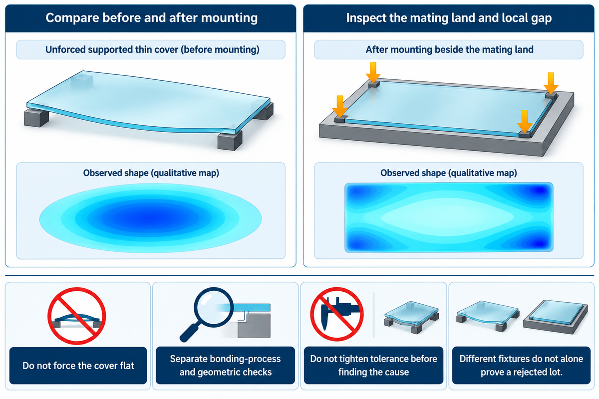
A bubble, uneven seal or distorted image doesn’t uniquely identify glass bow. Compare the cover’s surface map with the mating surface and assembly behavior before changing the flatness specification. The documented effect of mounting forces on thin optics makes fixture induced shape a reasonable cause to be investigated.
Do
- Compare the same part before and after the specified mounting step to see whether restraint makes it bend.
- Inspect the mating land and local gap where the defect occurs.
- Separate contamination and bonding-process checks from geometric checks.
Don’t
- Reject a lot because two different fixtures give different numbers.
- Force the cover flat and report the result as free-state form.
- Reduce the tolerance before connecting the measured shape to the failure.
Keep the measurement point connected to the finished glass manufacturing sequence. If the result varies after mounting, check the restraint and assembly loading conditions. If a visual defect persists despite a suitable geometric gap, the bonding process needs to be investigated. Adjust the process only after determining the cause of the observed defect. A surface map can show a broad curve; however, a map by itself doesn’t identify the cause.
Compare quotes at the same finished-part condition

Comparable quotes describe the same finished cover and inspection definition. Ask each glass company to quote against the drawing revision, controlled region and reporting method together. (Note: Uncertainty-aware acceptance is part of that agreement when results get close to a boundary, not an adjustment made after a disputed shipment.)
Engineering should establish the usable assembly window; Quality should agree the measurement procedure; Procurement should compare the resulting offers. Ask the manufacturer to separate any added inspection or process cost from the base part cost. Finance can then compare a tighter purchase requirement with a design change using actual quotations, instead of an assumed precision premium.
For a development trial, request a defined sample of finished covers and correlate measurements on those same parts. One sample isn’t evidence of production consistency. Discuss the required geometry through Saiwei’s custom cover glass service, with the application and drawing attached.
Send the gap requirement with the drawing
Include the controlled face, bonding or seal region, finished condition and proposed measurement setup. Ask for a feasibility response and a sample-inspection plan for that specification.
Frequently Asked Questions
Is glass perfectly flat?
No real glass surface is perfectly flat at every measurement scale.
A usable requirement defines how much departure from an ideal plane is acceptable over a stated area and in a stated support condition. A small optical measurement aperture, a full display cover and a perimeter sealing land can produce different results. Specify the area and method before comparing two reported flatness values, including any excluded border and the way the part is supported.
What is the ASME Y14.5 standard for flatness tolerance?
ASME Y14.5 defines dimensional and geometric specification language.
A surface flatness callout describes a tolerance zone between two parallel planes. The designer selects the allowed separation for the functional requirement; the standard’s public catalog doesn’t supply a universal display-cover acceptance value. For thin glass, agree how the part is supported or restrained during measurement. That inspection condition must not be confused with a datum reference for a separate orientation requirement.
What are the ASTM glass standards?
ASTM glass standards have distinct product and process scopes.
C1422/C1422M-26 addresses chemically strengthened flat glass and includes electronic-display applications in its public scope. It also explicitly excludes end-use performance from that scope. Select the exact document and edition for the material and application, then add the assembly geometry and measurement conditions required by the drawing. A standard relevant to architectural glazing doesn’t automatically settle a display-cover bonding requirement.
What thickness is plate glass?
Plate glass is not a single thickness.
For a display cover, specify the nominal sheet thickness and its permitted variation separately from surface flatness. Thickness alone doesn’t establish whether the finished cover will fit a bonding gap.
Is flatness tolerance the same as smoothness?
No. Surface form and surface texture describe different scales of geometry.
A polished surface can remain bowed across the part, while a comparatively rough surface can have a small overall form error. Keep roughness values such as Ra separate from a flatness specification.
Can a thicker adhesive compensate for glass bow?
A different bonding process can sometimes accommodate a different gap.
Adhesive thickness isn’t a universal allowance for glass bow. The proposed adhesive must work across the actual local gap range and under its specified lamination or cure conditions. Confirm optical appearance, adhesion and durability for the resulting assembly before relaxing the glass requirement. Follow the adhesive supplier’s applicable process data.
What should accompany a supplier flatness report?
Request enough information to repeat the result on the same finished part.
The report should identify the controlled face, measurement area, units, evaluation method and drawing revision. It should describe the support or restraint, part orientation and any excluded border or feature. Request the measured map when a single maximum value can’t show the sealing land or bonding region that matters. Compare the supplier’s setup with incoming inspection before treating a difference as a rejected part. Record how instrument uncertainty and sampling affect the agreed acceptance decision. If you need evidence of production consistency, ask for a defined sample of finished parts rather than assuming that one polished development sample represents every lot. Keep those observations separate from claimed process capability until an appropriate capability study exists.
Technical basis: Public standards scopes, metrology research, and named material-supplier publications, checked in October 2026. The gap example uses stated hypothetical inputs. It isn’t a Saiwei test report, or a guaranteed production tolerance. Paywalled standard clauses and the optical-bonding paper’s full text weren’t accessed.
References & Sources
- ASME Y14.5-2018 (R2024): Dimensioning and Tolerancing, official catalog.
- ISO 10579:2010: Non-rigid parts, public abstract.
- ISO 14253-1:2017: Conformity decision rules, public abstract.
- ASTM C1422/C1422M-26: Chemically Strengthened Flat Glass, public scope.
- NIST thin-optics surface-form metrology research, Chu and colleagues, 2010.
- On the Enduring Appeal of Least-squares Fitting in Computational Coordinate Metrology, Srinivasan, Shakarji and Morse, 2013.
- Optical bonding process of flat panel displays and their critical-to-quality factors, 2023, public abstract.