
Get in Touch with Saiweiglass



Updated October 2026
Cover glass corner radius design consists of three checks. The first is whether the complete outline fits its pocket. The second is whether the finished edge meets the agreed damage limits. The third is whether the assembled display survives its intended use. A nominal radius can’t answer all three. Start with the mating geometry, then agree on finishing and inspection before releasing the drawing.
A cover can clear every straight wall and still touch a housing corner. Another can fit perfectly but arrive with edge damage. Treating both failures as a request for “more rounding” sends the fabricator an incomplete instruction. This describes external corners of flat electronic display covers. The wider custom cover glass guide covers material, usage and application choices.
Quick Specs: what the corner detail must identify
- Plan view: full width, height, corner shape and drawing datums.
- Section view: glass thickness, chamfer or edge rounding, and finish.
- Assembly view: pocket, permitted placement and functional keep-out.
- Acceptance: finished condition, measured contour and damage criteria.
No universal minimum radius or chip-size limit is established by the sources reviewed here.
Three different geometries share the word radius
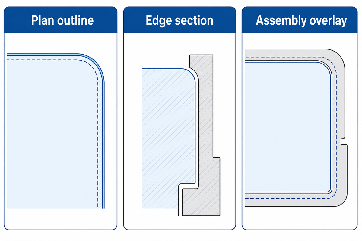
A corner radius, in plan view, provides the outline shown face-on. Edge-section rounding specifies the shape through the glass thickness. A mating pocket radius is for the enclosure. All three of these can appear on the same assembly drawing; however, they control different surfaces and require different inspection views.
A rounded corner replaces a square vertex with a curved transition. A circular arc requires both a radius and a defined position. “radius corners” leaves too much undecided. Depict the corner in a plan view and the edge in a separate section. A pencil edge can soften the through-thickness profile without changing the specified outside outline to a larger round in the plan view. A bent glass panel’s curvature in a specified direction is a separate specification.
| Drawing view | What it controls | What it does not establish |
|---|---|---|
| Plan outline | Outside corner, width, height and tangency | Edge-section finish or strength |
| Edge section | Thickness, chamfer, rounding and finish | Clearance inside the enclosure corner |
| Assembly overlay | Glass position, pocket and keep-out relationships | Acceptance of a manufactured glass edge |
This is a framework for drawing reviews, not a prescribed standard. ASME Y14.5-2018 (R2024) provides dimensioning and tolerancing conventions; its public overview doesn’t select a tolerance for your cover. Use the cover glass drawing checklist for the full package, then make the corner detail unambiguous within it.
Choose radius from the complete assembly envelope
Select the radius from the complete mating outline, not by subtracting a clearance from an isolated housing dimension. Check the glass, pocket and functional keep-out together. A smaller radius, when combined with a glass of a particular width and height, can take up more corner and interfere with the pocket even when the gaps at straight edges look correct.
What should be considered when designing the corners of cover glass?
Take into consideration the glass outline, the mating pocket, the permitted assembly movement, the edge section, and the space required for printing and bonding. Determine their finished relationship. Then distinguish nominal clearance from worst-case fit: a nominal drawing overlay doesn’t include every dimensional or positioning variation, and it can’t establish resistance to chipping.
3-Contour Corner Review
Functional keep-out or adhesive land should be compared with the internal pocket and glass outline in a drawing overlay. A correct size at straight edges doesn’t guarantee corner fit. A nearby opening creates an edge distance question; review it with the hole to edge distance review and don’t assume a convex radius solves it.
Engineering Note: a nominal fit example, not a recommended clearance
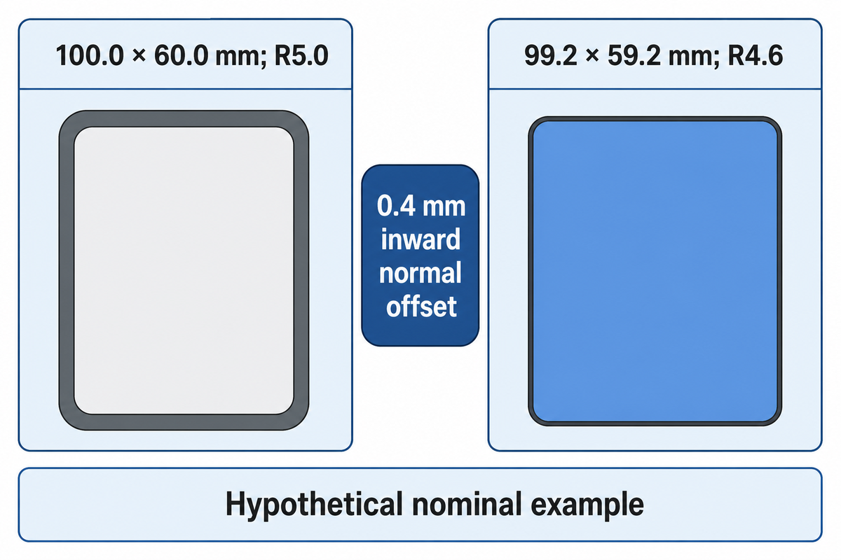
Assume an internal pocket measuring 100.0 × 60.0 mm with tangent R5.0 corners. Offset the entire outline inward along its normal by 0.4 mm. The ideal glass outline becomes 99.2 × 59.2 mm with R4.6 corners: width and height each decrease by 0.8 mm, while each arc radius decreases by 0.4 mm.
This construction assumes centered, aligned outlines and four tangent quarter circles, with clearance smaller than the pocket radius. It assigns no dimensional tolerance. Specify the actual datums and tolerances under the agreed drawing convention, such as ASME Y14.5, after reviewing the assembly requirements.
Keeping glass width and height, set the corner to R3.0. At the 45-degree point, the glass extends approximately 0.263 mm outside the pocket arc, despite retaining 0.4 mm gaps along the straight sides. Checking side gaps alone can miss corner interference, as demonstrated here. The example doesn’t compare the fracture strength of the two shapes.
For a rounded rectangle, area equals width × height − (4 − π) × radius². Thus, increasing radius at fixed width and height removes corner material. See what that change does to the actual bond land and printed border. If the cover is bonded, the optical bonding interface should be included in the review, rather than treating the visible edge as the only functional boundary.
Why rounded glass can still chip
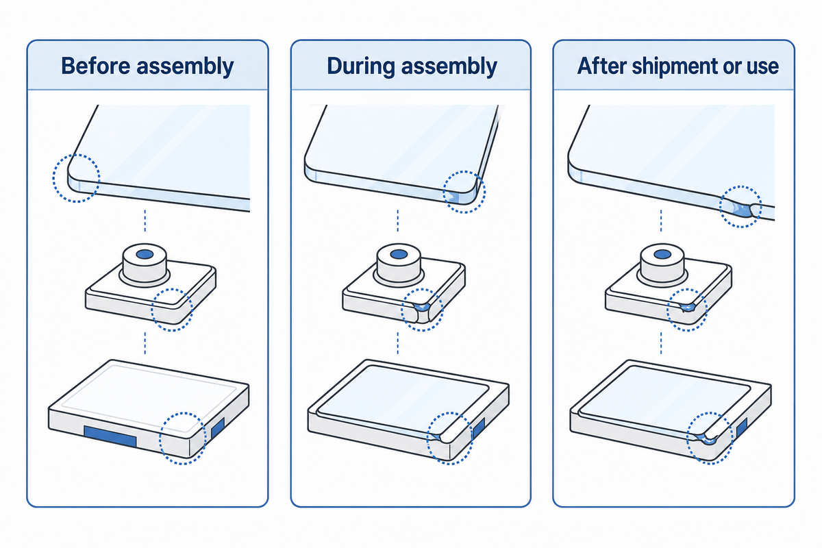
Glass can still chip, even if rounded, since its edge doesn’t describe the flaw population, contact conditions or loading history. First determine when and where the damage occurred. Incoming damage, chips at locating features and damage first seen after transport call for different analyses; increasing radius before locating the cause can make useful evidence obscure.
NASA/JPL’s 1985 study of glass breaking strength (accessible to the public via abstract) mentions surface flaws and remaining surface compression. This work concerns photovoltaic glass; its mechanism discussion is useful here, but its strength values are not design allowables for an electronic cover.
- Damage present before assembly: retain the incoming inspection record and examine the affected edge location.
- Damage first seen during assembly: compare the chip location with hard contacts, locating features and the assembly operation.
- Damage found after shipment or use: retain packaging, handling and service observations before deciding which process to change.
As an example of a first article disagreement: incoming photos show intact glass corners, but chips are present next to the same housing locator after assembly. This is grounds for an investigation on the locator and the assembly process, but isn’t evidence that the provided glass had no smaller defects, nor that a radius change would correct production.
Inspection also identifies a particular instance in time. Wiederhorn’s glass crack-growth experiments demonstrated that crack velocity was a function of the applied stress and the level of environmental water vapor. The mechanism can inform questions about sustained loading and service conditions, but does not provide a prediction of life for this assembly.
For unexplained failures, NIST’s 2026 fourth-edition fractography guide is a reference for failure investigation methods. Keep the damaged part and its history. A measured radius and glossy edge aren’t substitutes for identifying the failure origin.
Match the edge finish to the contact and inspection plan
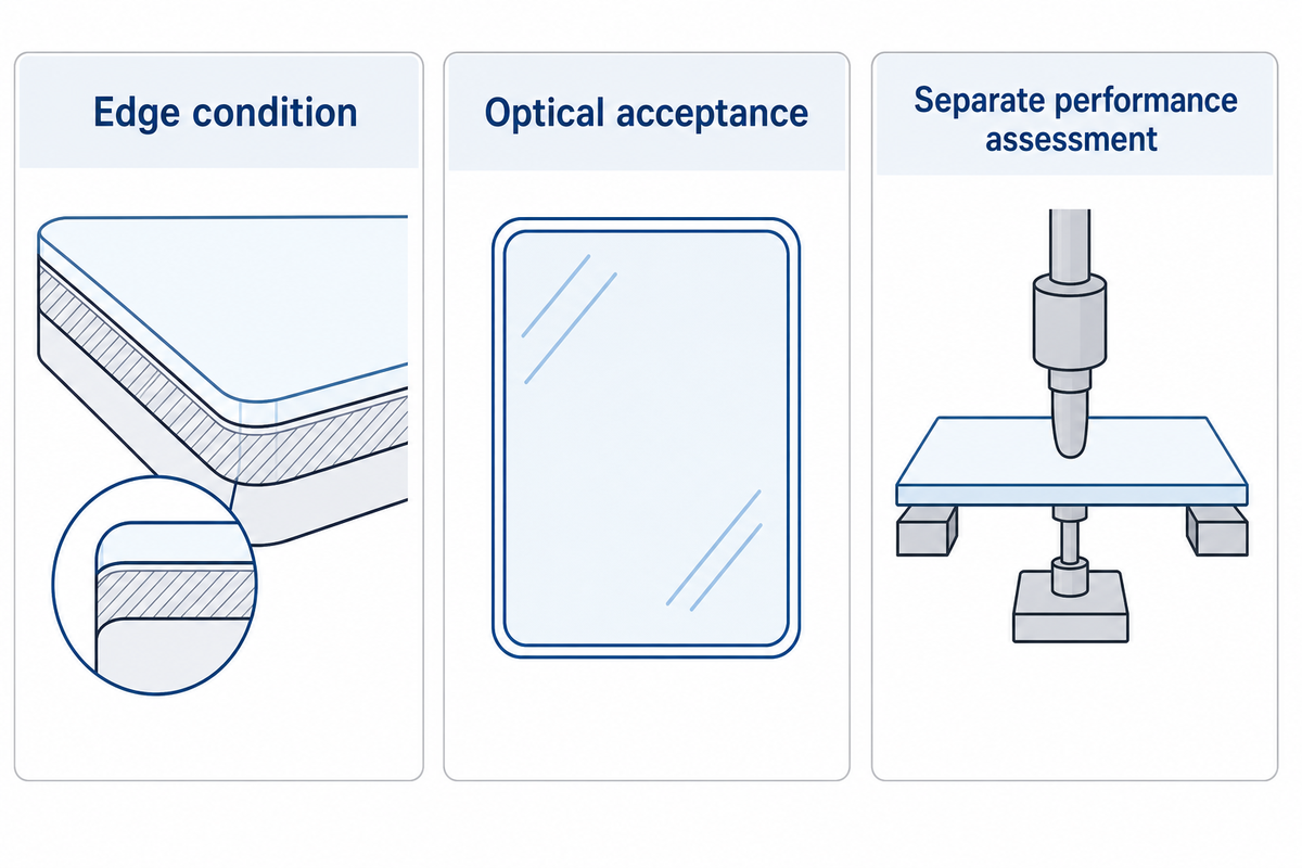
Specify edge finish and corner radius separately, and evaluate each proposed change against the observed problem. An improvement of the finish addresses the processed edge, and an adjustment of an outline addresses a problem in geometry. Neither improvement proves that the assembly meets its strength, appearance or optical requirements.
In their 2020 study, Bukieda and colleagues integrated microscopy into four-point bending tests of annealed building-glass beams. Similar appearing scratches can behave differently, and the authors mentioned the limitation of 2D images for determining scratch depth. Their industrial partners were Artifex, a manufacturer of abrasive wheels, and Frank Ahne, a processor of glass, and these weren’t SW Glass tests.
“not every clear defect is causing an early breakage”
Bukieda et al., 2020, discussion of annealed building-glass edge tests
The lesson is more specific than “polishing doesn’t work.” A smooth finish is one of the characteristics of a component, not strength certification. A sleek appearance doesn’t prove that a corner is durable. Agree on both the required edge condition and the separate performance assessment for the product, including applicable safety requirements.
Do
- Separate outline and edge-section requirements.
- Record damage location and inspection stage.
- Change one suspected cause in a controlled sample comparison.
Don’t
- Use visual gloss as a strength rating.
- Replace a fit check with a finishing instruction.
- Copy building-glass test strengths into a thin-cover specification.
Keep optical acceptance in the same change review. A 2014 study of chemical polishing on soda-lime mobile cover glass reported different levels of strength and transmittance for the treatments studied. These results can’t be generalized to mechanical polishing. Likewise, a specified anti-glare gloss level addresses a surface appearance issue and not a corner-fit issue.
Confirm material and processing sequence before release
Agree on material, thickness, strengthening route and the condition in which the corner will be inspected. Ask the fabricator to identify when outline machining, edge finishing and any rework happen, relative to strengthening and coatings. A common drawing shape doesn’t demonstrate that different material and process routes produce equivalent finished parts.
If a quote names tempered glass as an option, require the supplier to identify the actual strengthening process. The public scope of ASTM C1422/C1422M-26 provides a useful distinction. It classifies chemical strengthening by surface compression and depth of compression rather than modulus of rupture, and does not establish end-use performance. Therefore, a material classification would not be an approval of a finished corner.
Can display cover glass be bonded directly to the display?
Bonding is an assembly-design decision that must account for the selected glass, surface condition, printing, adhesive and display stack. Identify the prepared glass surface, transparent viewing window and printed border, including the required color. Show the required corner bond land and keep out on the assembly detail. Agree on the bonding process and acceptance tests with the responsible suppliers. The corner-radius callout, in itself, doesn’t confirm bonding performance.
The chemical strengthening overview helps distinguish the material route from the finished part specification. Damage history is also important. Egboiyi’s 2022 Michigan Technological University dissertation abstract discusses interactions of ion-exchange residual stress with cracks introduced at different stages. It doesn’t give a universal machining sequence.
- Name the material and required strengthening condition.
- Identify the final processing stage represented by the inspection sample.
- Require proposed rework to be reviewed against the approved drawing and acceptance plan.
- Record which supplier owns the glass, coating and bonding interfaces.
This raises a release question. Can the agreed process manufacture the specified finished part? This avoids using the assumption that a familiar glass name guarantees the corner’s behavior.
Inspect the finished corner against the drawing
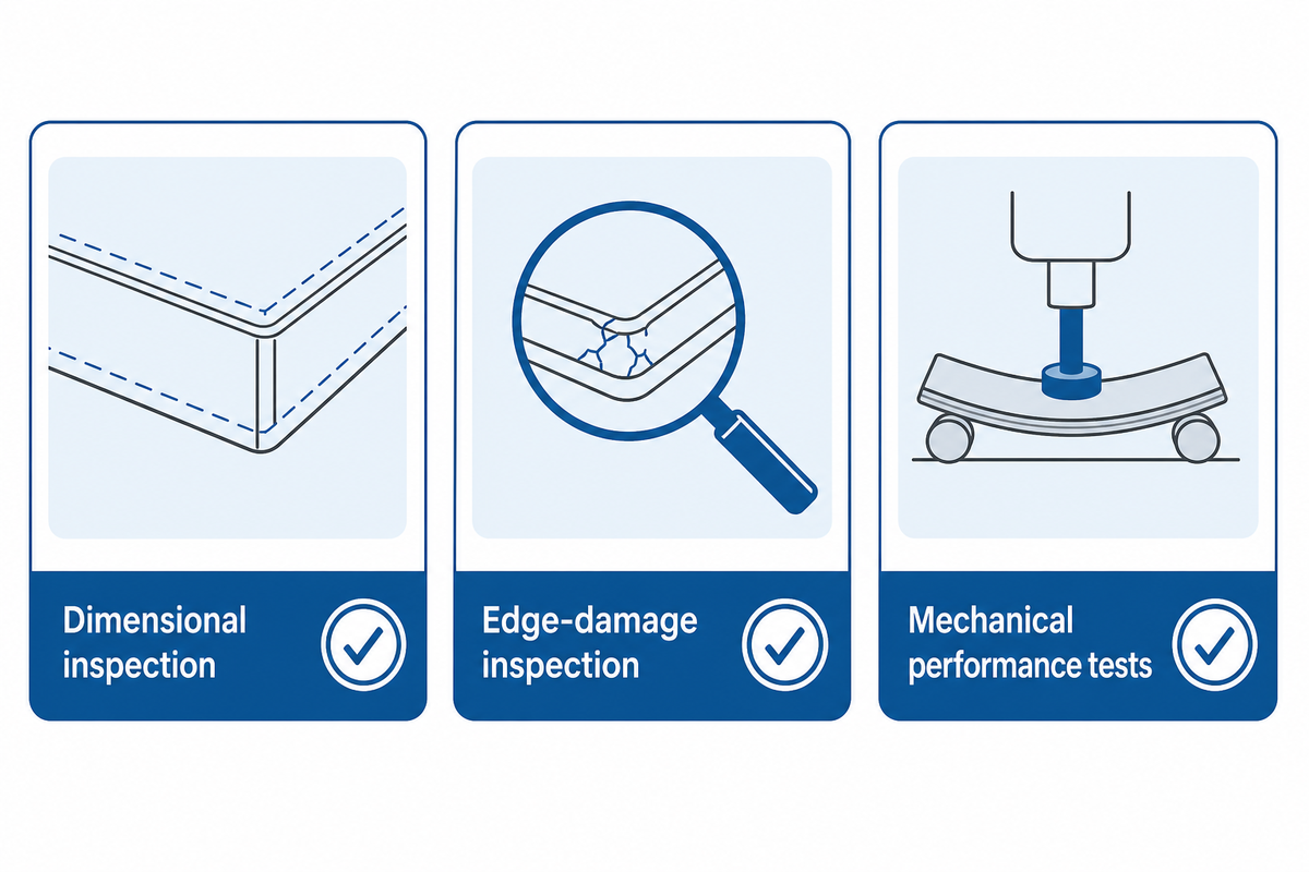
Use the drawing’s datums to inspect the completed finished contour and determine acceptance as agreed. A fitted radius value alone may miss profile shift, local flat and/or tangency. Maintain separate records for dimensional inspection, edge-damage inspection and mechanical performance tests, so that a pass in one isn’t considered a pass in the others.
The public description of IEC 61747-40-1:2019 explicitly concerns cover-glass-level mechanical testing. It does not qualify the finished display assembly. Likewise, a bonding or readability review, such as the sunlight-readable display assembly review, addresses a different set of requirements.
The inspection table below illustrates how to document a review of an example illustrative drawing. It provides dimensions only from the ideal pocket example provided above. The acceptance decisions are separate from the nominal dimensions; no universal production tolerance or cosmetic chip limit is recommended.
| Inspection category | Filled example | Release evidence to request |
|---|---|---|
| Drawing identity | Illustrative CG-01, revision A | The same controlled revision on the order and inspection report |
| Nominal outline | 99.2 × 59.2 mm; four R4.6 corners | Measured contour against the agreed drawing limits |
| Nominal pocket | 100.0 × 60.0 mm; four R5.0 corners | Assembly evaluation including permitted part positions |
| Offset premise | 0.4 mm inward normal offset | Confirmation that the real design’s tolerance analysis is separate |
| Observed boundary | Outside plan silhouette | Method that identifies that boundary despite the edge-section finish |
| Finished condition | Sample after agreed final processing | Traceable material and process condition on the sample record |
| Edge section | Separate section detail on CG-01 | Confirmation of the agreed chamfer or rounding and finish |
| Functional boundary | Bond land and printed-border keep-out | Assembly overlay showing the approved functional area |
| Performance scope | Glass-level test and assembly test recorded separately | Applicable method, sample condition and acceptance basis for each |
| Damage record | Incoming, after assembly, after agreed validation | Location-tagged observations against approved defect criteria |
For instance, two reports may both say R4.6 while having different edge detection or alignment methods. Find out which contour was measured and how it was aligned. Settle that difference before you assume the reports are comparable. In case of a failure, keep the location-tagged records for further analysis as detailed in NIST’s fractography guidance.
Compare quotes without hiding corner-related costs
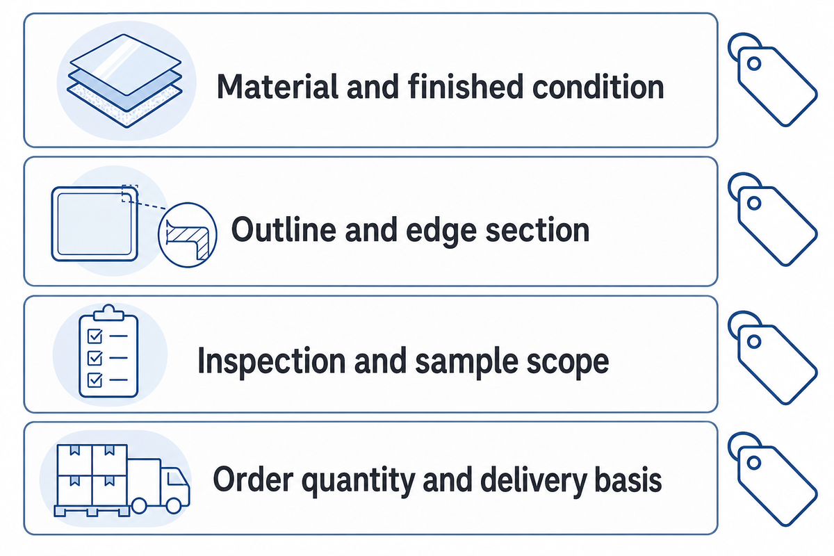
Compare quotes against the same drawing revision, material, finish, quantity and inspection requirement before attributing a price difference to corner radius. Ask each supplier to identify included operations and exceptions. This is a framework for purchasing, not a source of market prices, or a requirement to disclose suppliers’ internal margins.
ASME’s dimensioning overview gives the drawing language background. The comparison below is an editorial worksheet, to make offers readable. The standard doesn’t define the cost of a glass corner.
| Keep identical | Ask suppliers to identify | Buying decision |
|---|---|---|
| Material and finished condition | Any proposed substitution or process change | Review the change before comparing price |
| Outline and edge section | Included machining and finishing operations | Separate an equivalent offer from a changed part |
| Inspection and sample scope | Included reports and separately priced sample work | Budget for the same release evidence |
| Order quantity and delivery basis | Setup charges, recurring price and explicit exclusions | Compare totals on one purchasing basis |
Procurement can compare the offer, engineering can approve drawing exceptions, and quality can confirm the evidence needed for release. A comparable total without an invented percentage saving is given to finance. If a lower quote doesn’t include an inspection, resolve that difference before calling it a cheaper corner.
Send a complete corner design package to your fabricator
Send the controlled corner detail along with the mating-pocket drawing, functional keep-out, and acceptance plan. Request written identification of any exception before approving samples or production. A finished part is to be agreed upon along with the inspection basis rather than having a general assurance that rounded glass can be made.
SW Glass’s custom cover glass configurator shows offerings of custom shapes and flat polished, beveled, pencil and seamed edges. That public offering does not set a minimum radius for your design. When mechanical testing is specified, distinguish the IEC cover-glass test scope from the assembly validation you are seeking.
- Freeze the review drawing. Identify the plan outline, edge section and mating boundaries.
- Agree on exceptions and evidence. Record material, processing and inspection responsibilities.
- Review representative finished samples. Compare dimensional, damage and assembly results before production release.
Key takeaway
The 3-Contour Corner Review separates fit from finish and performance: review the glass outline, pocket and functional keep-out, then approve the actual finished part against its own acceptance plan.
Cover glass corner radius design FAQs
Does thicker cover glass always provide better protection?
Thickness alone does not establish assembled protection.
A thicker sheet is not a substitute for checking the complete design. Material, strengthening, edge condition, support and the applied loads still need review. A thickness change can also alter the enclosure and bonding arrangement. Approve thickness against the actual loading and touch requirements, then verify the finished design with representative samples.
Can the same cover glass specification be used for different display sizes?
A change in display size requires a fresh fit and assembly review.
Do not transfer it unchanged. A different display size can alter unsupported span, mounting details, adhesive land and the relationship between the glass outline and enclosure corners. Recheck the drawing and assembly envelope for each size. Retain common material or finish requirements only after confirming that their original acceptance conditions still apply.
Can cover glass affect touchscreen sensitivity?
The cover specification should be approved as part of the complete touch system.
The glass and the layers between a finger and the sensor form part of the touch system. Confirm the proposed material, thickness, printing and bonding arrangement with the touch supplier. A corner-radius drawing cannot establish touch performance. Test the assembled design, including intended operating conditions and any required glove use before release.
Why is flatness important for display cover glass?
Flatness is a separate requirement from the outside corner profile.
Flatness affects how a panel sits on its support and meets its bonding surfaces. A corner outline can pass dimensional inspection while the assembly still has uneven contact. Define flatness separately and then inspect it in the agreed finished condition.
Can a radius measurement alone verify the corner profile?
A fitted radius value cannot describe every feature of the actual corner contour.
A fitted circle describes only one aspect of the corner. A local flat, tangency error or shifted contour may still matter to assembly fit. Specify the datum alignment, inspected contour, measurement method and acceptance limits together. Ask for the actual profile result on representative finished parts, not just a nominal radius copied from the drawing. Confirm whether the inspection follows the maximum silhouette or another defined edge, particularly when chamfers or rounded cross-sections change the visible boundary at the inspected location.
Is there a universal minimum corner radius for display cover glass?
The reviewed sources do not establish a universal minimum external corner radius.
Material, thickness, edge treatment, process and assembly conditions differ. Ask the fabricator to assess the actual corner detail and confirm the agreed dimensions and acceptance method in writing. A value supplied for another product is not automatically suitable for yours.
What should change if first-article samples chip only after assembly?
Investigate the damage location and assembly operation before changing the radius.
Preserve the incoming and post-assembly observations before changing the drawing. Compare chip locations with housing contacts, locating features, adhesive interruptions and handling points. Then isolate the suspected variable in representative samples while keeping other conditions consistent. Increasing the radius may help a geometric conflict, but it cannot establish that edge defects or assembly loads are controlled. Agree who will inspect each stage and which observations permit production release, so the proposed correction can be checked against the failure.
Preparing a custom cover glass enquiry?
Include the corner drawing, mating outline and required inspection evidence with your request. Ask SW Glass to review the actual design and identify any exceptions before you approve the sample scope.
Related Articles
References & Sources
- Y14.5-2018 (R2024): Dimensioning and Tolerancing ASME public catalog.
- Glass breaking strength: The role of surface flaws and treatments D. Moore, NASA/JPL, 1985; photovoltaic-glass scope.
- Fractography of Ceramics and Glasses, fourth edition George Quinn, NIST, 2026; public abstract.
- Study on optical quality and strength of glass edges after grinding and polishing process Bukieda et al., 2020; annealed building-glass study with industrial partners.
- Influence of water vapor on crack propagation in soda-lime glass Wiederhorn, 1967; public abstract.
- Chemical polishing study of soda-lime mobile cover glass Maeng et al., 2014; public abstract, industry-linked authorship.
- C1422/C1422M-26: Chemically Strengthened Flat Glass ASTM International public scope, 2026.
- Fracture Mechanics of Chemically Strengthened Glass: Experiment and Modelling Benedict Osobomen Egboiyi, Michigan Technological University, 2022; dissertation abstract.
- IEC 61747-40-1:2019 cover-glass mechanical testing guidelines IEC public description.
Research checked October 2026. Numerical geometry examples and worksheets are illustrative constructions, not SW Glass production measurements. Standard references use publicly available descriptions; purchased test procedures weren’t reproduced.

![Top 20 Chemically Strengthened Glass Suppliers [2026]](https://saiweiglass.com/wp-content/uploads/2026/08/chemically-strengthened-glass-suppliers-featured-768x512.png)