Get in Touch with Saiweiglass



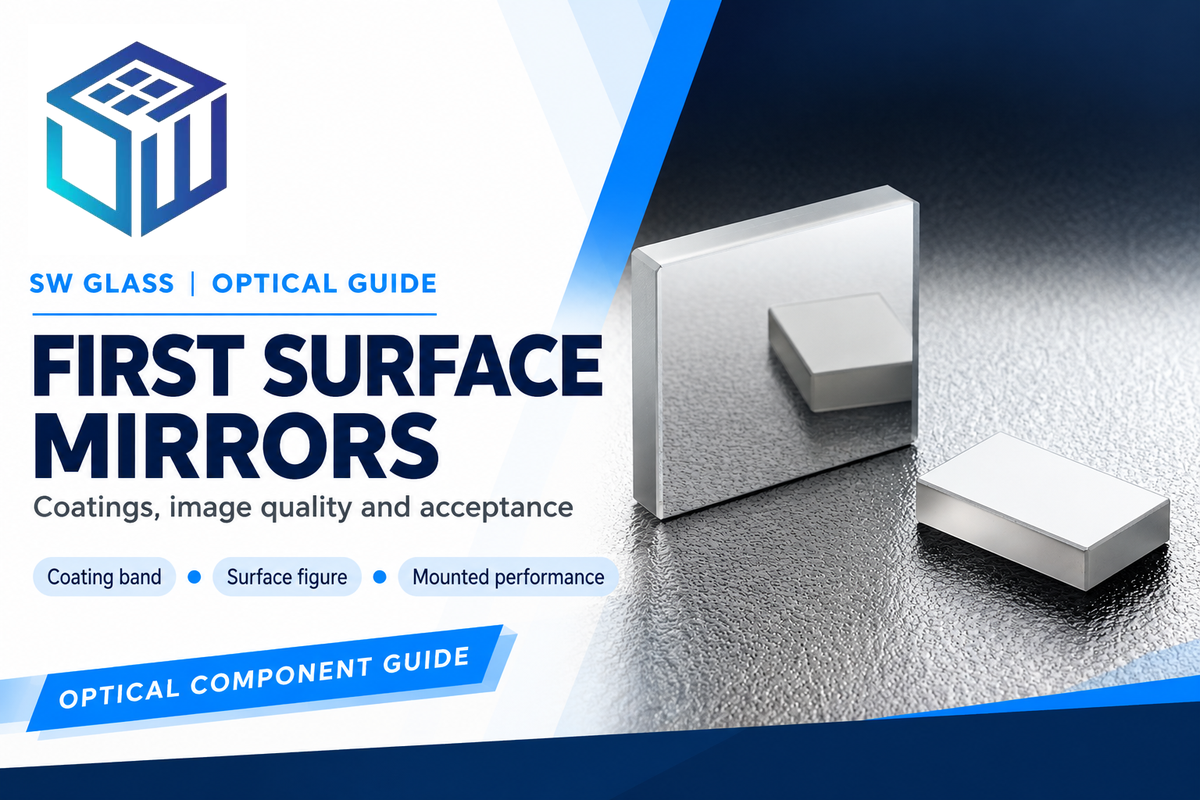
A first surface mirror has a reflective coating on the side that faces the incoming light. The main beam is reflected without passing through the supporting glass. The arrangement eliminates the front-glass reflection path of an ordinary back-coated mirror. This makes a first surface mirror useful when a faint secondary image would interfere with imaging or measurement.
Selecting one still means matching the coating to the light and the finished surface to the instrument. A bright reflection alone says little about flatness, scattered light or performance post-mounting.
Quick specifications to establish
Optical inputs: wavelength band, angle of incidence, polarization and clear aperture.
Mechanical inputs: substrate, thickness, shape and mounting arrangement.
Acceptance: reflectance curve, finished surface figure, defect inspection and cleaning instructions.
First surface mirrors reflect light at the front coating. They avoid the bulk-glass path of back-coated mirrors. Choose the coating for the operating wavelength and specify the finished, mounted optical performance.
Key points
- High reflectance doesn’t establish image quality.
- A protective overcoat can cover a first-surface coating; the bulk substrate remains behind it.
- Reflection losses accumulate along a folded optical path.
- Coating stress and the mount can change a mirror’s finished shape.
What Is a First Surface Mirror?
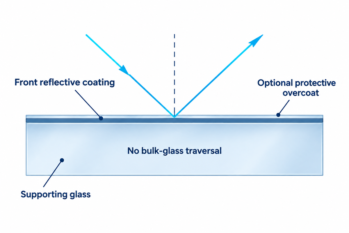
A first surface mirror, also known as a front-surface mirror, has the reflecting layer in the incoming beam’s path before the supporting substrate. Designers use a first surface mirror to eliminate the refraction through the supporting substrate before the main reflection occurs.
This front-coated arrangement in scientific instruments is described in Florida State University’s optics primer. Freshly deposited aluminum has about 90 percent reflectance over most of the ultraviolet, visible, and near-infrared spectral regions. A mirror may have a thin protective layer over a metallic coating. That layer is part of the coating system and doesn’t turn the mirror into an ordinary reflector viewed through a thick glass plate.
The shape that the reflective surface follows is provided by the substrate. Even though the useful beam doesn’t pass through the substrate, its material, finish and support still matter. In our optical glass guide, we’ve discussed the various choices in detail. For mirrors, it’s the reflecting surface that should be considered rather than assuming a particular glass name establishes precision.
First Surface vs Second Surface Mirror: The Optical Difference
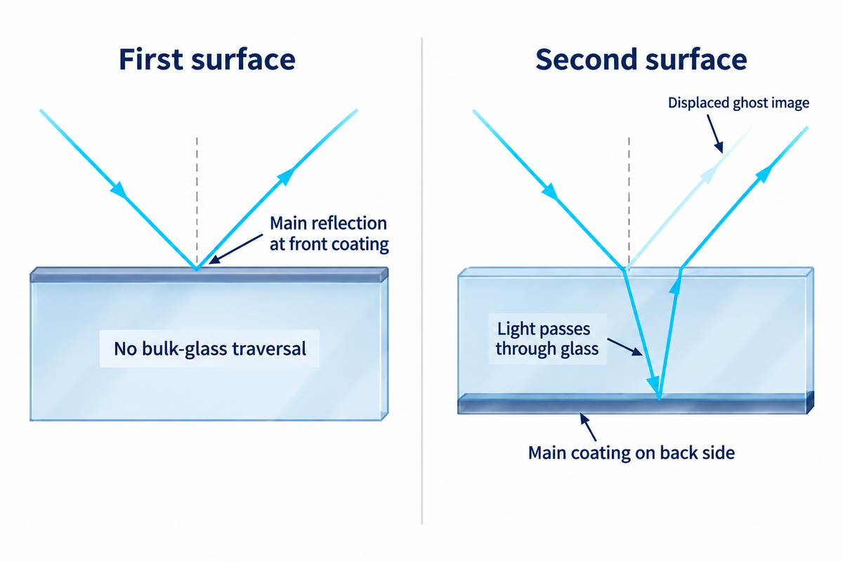
Compared to a first surface mirror, a second surface mirror sends light through a transparent substrate before it strikes the main reflective coating. Some light can reflect from the front surface of the glass as well. The displaced reflection can appear as a ghost image next to the intended reflection, especially in an angled optical path.
First surface
- Main reflection occurs at the front coating.
- No bulk-glass traversal before reflection.
- Coated face needs careful handling.
- Useful for folded imaging and measurement paths.
Second surface
- Main coating sits on the back side.
- Light passes through the supporting glass.
- Front glass protects the reflective layer.
- Extra surface reflections may be visible.
As explained by Edmund Optics, ghost reflection and dispersion happen in this geometry. Eliminating that particular glass path doesn’t get rid of all stray light. Other windows, lens surfaces, and/or other internal reflections can affect the picture.
Let’s say we have a camera inspecting printed edges through a folded path. After installing a standard mirror, a front-glass reflection ghost can be seen as a duplicate edge. Edmund Optics says that this is caused by substrate reflection. A front surface coating addresses this reflection, and a bent mount needs to be corrected separately. The function of the anti-reflective coating is different from that of the reflective coating of a mirror.
Mirror Coatings: Aluminum, Silver, Gold and Dielectric
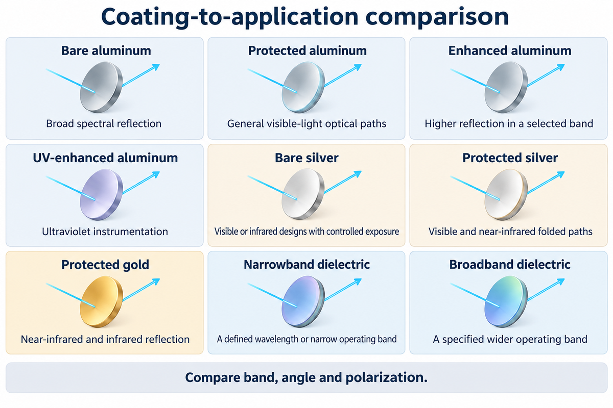
The choice of mirror coating is largely dependent on the operating spectrum, the angle of incidence and the state of polarization. Aluminum, silver and gold exhibit different spectral behavior, while a dielectric stack can be designed to target a specified band. Protection and enhancement layers also change performance, so the name of the coating material alone doesn’t allow comparison of finished mirrors.
It’s important to review the coating curve, especially if the beam contains ultraviolet light, or is incident at an oblique angle.
| Coating family | Potential use | Question for the supplier |
|---|---|---|
| Bare aluminum | Broad spectral reflection | How will the exposed surface be handled and maintained? |
| Protected aluminum | General visible-light optical paths | What band and angle does the reflectance specification cover? |
| Enhanced aluminum | Higher reflection in a selected band | Where does the enhancement fall outside its useful band? |
| UV-enhanced aluminum | Ultraviolet instrumentation | Does the curve cover the exact UV wavelengths? |
| Bare silver | Visible or infrared designs with controlled exposure | What protection does the installation provide? |
| Protected silver | Visible and near-infrared folded paths | Which environmental and cleaning conditions are qualified? |
| Protected gold | Near-infrared and infrared reflection | Does the instrument require visible alignment light too? |
| Narrowband dielectric | A defined wavelength or narrow operating band | What happens at the working angle and polarization? |
| Broadband dielectric | A specified wider operating band | Are both polarization states covered throughout that band? |
For a concrete supplier example, Edmund Optics lists enhanced aluminum at average reflectance above 95% over 450–650 nm, and protected silver above 98% over 450–800 nm. These are band averages for their respective mirrors, not average reflectances for all aluminum or silver mirrors. Compare the same wavelength interval and measurement conditions, rather than selecting the largest percentage in a catalog.
Spectral selectivity also requires attention when using dielectric mirrors. A dichroic optical coating deliberately treats different wavelengths differently and thus shouldn’t be assumed to act like a neutral reflector across the entire visible spectrum.
Glass or Acrylic: Choose the Substrate for the Job
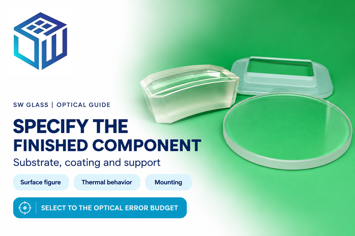
Glass and acrylic first surface mirrors should also be evaluated as finished components, and that evaluation should include optical acceptance criteria, support, and tolerance data. The reflecting surface is on the substrate, so stiffness, thermal behavior and manufacturing quality affect the final result. The coating, support, and tolerance should be selected to meet the optical needs of the instrument.
For applications requiring a specified surface figure and repeatable measurement, use documented optical glass. Fused silica and other low-expansion materials may be relevant when temperature changes matter; FSU’s primer discusses thermal stability when choosing a substrate. The required grade of the substrate is determined by the optical error budget, rather than the word “precision” on a product page.
For the decorative kaleidoscope, a buyer would likely look for available sheet size, ease of use, and a pleasing aesthetic. A kaleidoscope first surface mirror doesn’t necessarily have the same acceptance criteria as a metrology reflector. For an acrylic mirror project, examine the actual supported piece for image distortion, and confirm how it will be cut and fixed in place.
Thickness deserves its own drawing field. A thinner part may fit the enclosure but behave differently when supported. Request the completed dimensions and method of mounting in combination; don’t transfer a claim of flatness from an unmounted part to the mounted assembly.
Reflectance After Multiple Mirrors: A Worked Example
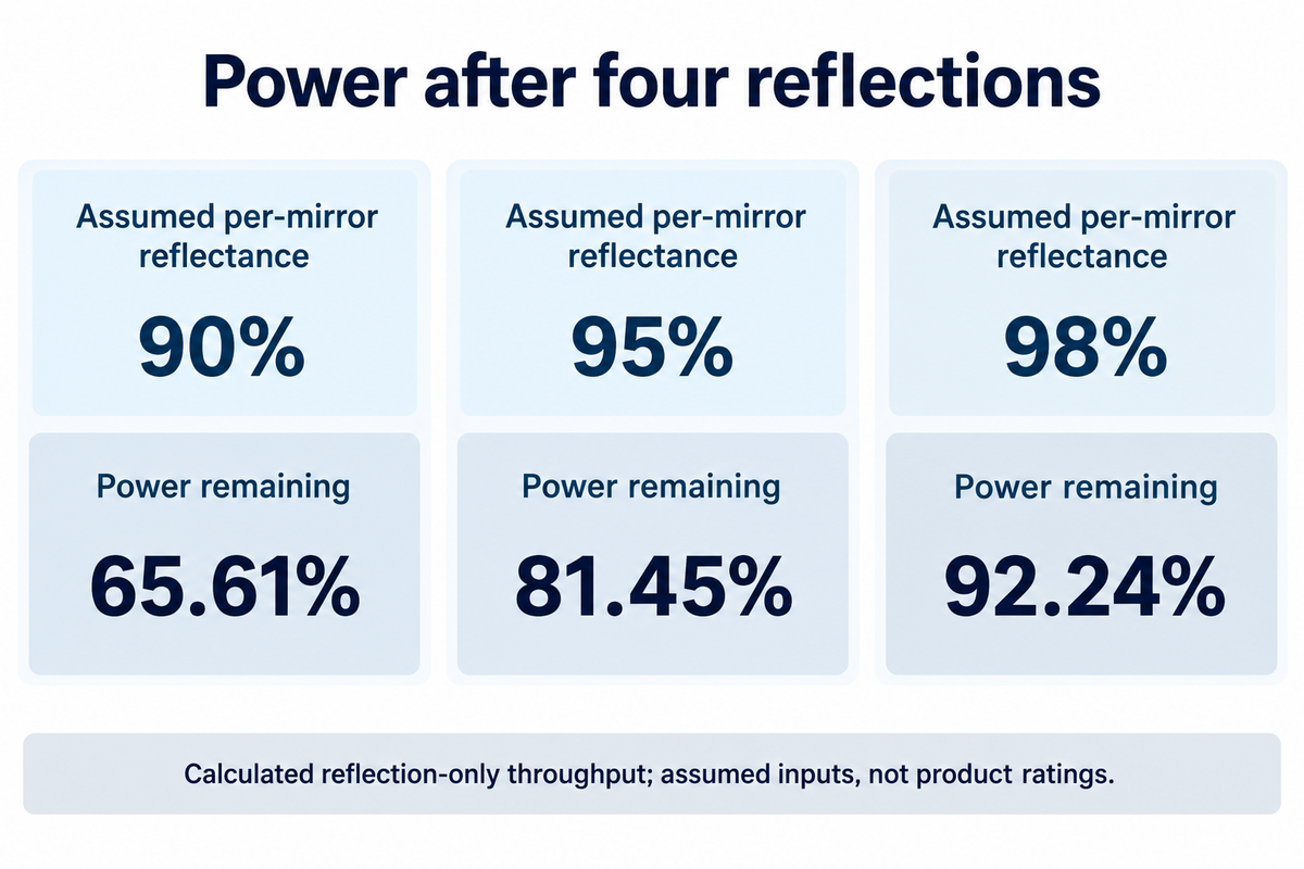
For power reflectances R₁ through Rₙ, the fraction of power remaining after several reflections is their product. If it’s assumed that each reflection is R, the power fraction that gets through is R raised to the power N. It’s an approximate calculation of reflected power; it doesn’t predict focus, contrast or image distortion.
4-Bounce Throughput Table
A 4-bounce throughput table compares power remaining after successive reflections using stated, constant per-mirror reflectance assumptions.
Let’s take the example of a folded instrument that uses four mirror reflections, each assumed to return 95% of the incident power under the relevant conditions. Using the reflection only calculation, the power that gets through is 0.95 × 0.95 × 0.95 × 0.95 = 0.81450625 or approximately 81.45%. The table extends the same calculation for other assumed inputs.
| Assumed reflectance per mirror | Number of reflections | Power remaining |
|---|---|---|
| 90% | 1 | 90.00% |
| 90% | 2 | 81.00% |
| 90% | 4 | 65.61% |
| 95% | 1 | 95.00% |
| 95% | 2 | 90.25% |
| 95% | 4 | 81.45% |
| 98% | 1 | 98.00% |
| 98% | 2 | 96.04% |
| 98% | 4 | 92.24% |
The mirror primer by FSU illustrates this loss accumulation. For a real instrument, reflectances applicable for the light reaching each mirror should be used. NIST’s polarization documentation explains why incident polarization matters. Reflections may change the polarization state, so using an unpolarized average throughout may lead to a misrepresentation of the chain.
The assumed table omits clipping, contamination and losses in other components. Losses in windows and lenses (determined from transmittance) should be accounted for separately. A deficit in throughput should be traced to these loss terms before buying a component with higher reflectance.
Specifications That Control Image Quality
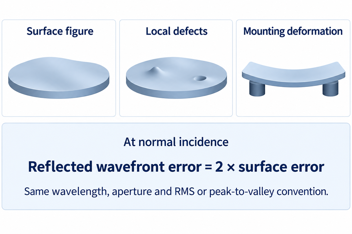
Besides reflectance, other factors can affect image quality, including surface figure, scattered light, local defects, and mounting deformation. Clark and co-workers examine the effects of mounting-pad size and deformation. These factors should be considered separately; the usable aperture should be defined, and the working surface should be assessed using measurements made after coating, within that aperture.
Surface figure refers to departure from a given plane. Reflected wavefront error describes the effect on the reflected wave. Alluxa’s technical explanation states that, at normal incidence, reflected wavefront error is twice the surface error. Compare values only for the same wavelength, same aperture, and the same RMS or peak-to-valley convention.
Scratch-dig and other surface imperfection requirements describe local defects. ISO 10110-7:2017 covers permissible imperfections such as local defects, edge chips and long scratches. Specify the defect inspection separately from surface figure, microroughness and scattered light so each requirement has an appropriate acceptance method.
Surface-scattering research at NIST describes the impact of microroughness, subsurface scattering and other defects. A haze or contrast problem in an imaging instrument therefore requires a different assessment than a displaced ghost image.
Define the circumstances under which measurements will be made. Coating stress can change the shape of the substrate; contact geometry and preload can change the shape again during installation. Clark, Penado and Cornelius studied deformation from different mirror-support contact areas. Request post-coating data and agree upon acceptance criteria for the mount.
Where First Surface Mirrors Are Used
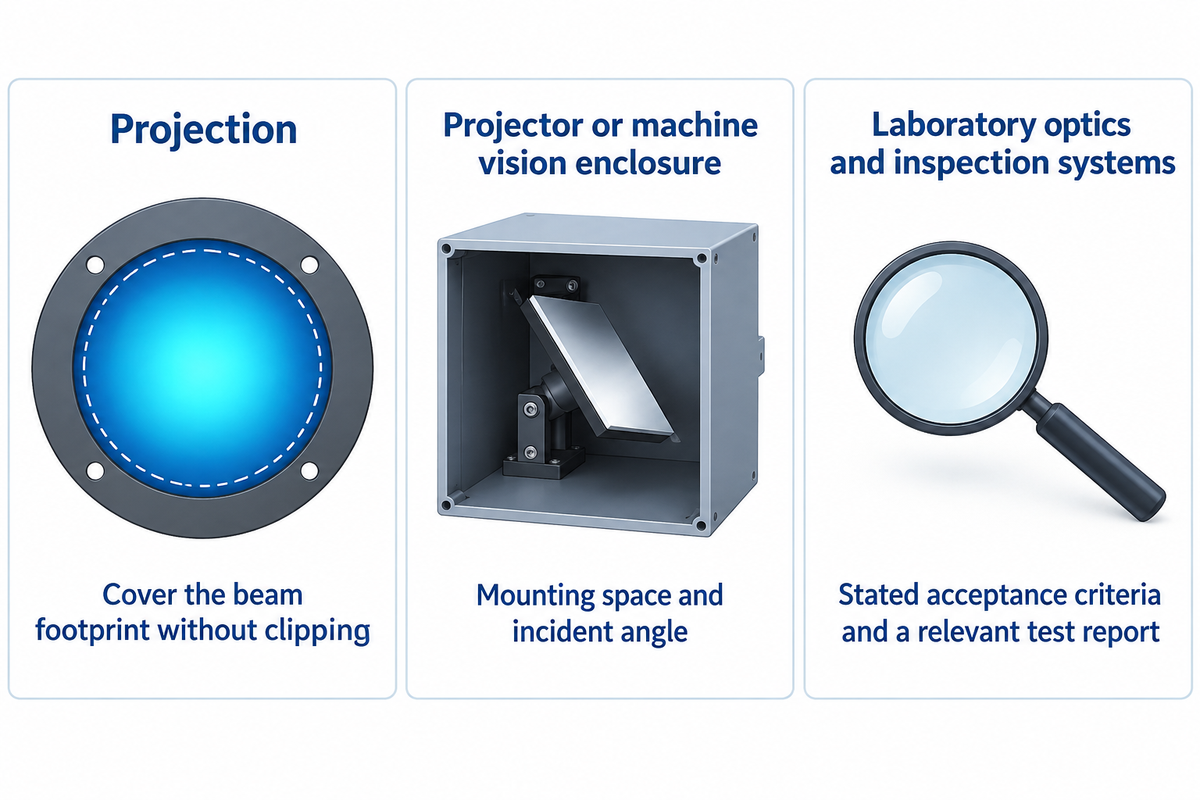
First surface mirrors are useful where an optical path needs to change direction without the extra glass traversal of a back-coated reflector. Various imaging, projection, and measurement systems can make use of this geometry, but each system will have its own requirements for coating band, usable aperture, and surface quality.
A rear projection system requires a mirror to cover its beam footprint without clipping. For a projector or machine vision enclosure, determine the available mounting space and the incident angle prior to selecting the nominal size. An oversized blank with poorly defined usable edges may not solve an aperture problem.
Laboratory optics and inspection systems often require a clearer traceability of figure and coating performance. Optical grade quality should mean stated acceptance criteria and a relevant test report, not merely an appealing reflection. This shouldn’t be left to the supplier’s judgment. Our photonics overview describes these and other components in more detail.
For alignment, compare a known target before and after installing a mirror. Consistent image shift after the mirror installation suggests a different issue from a distorted target and helps distinguish between an alignment issue and a surface or support issue.
First Surface Mirror Cleaning and Handling
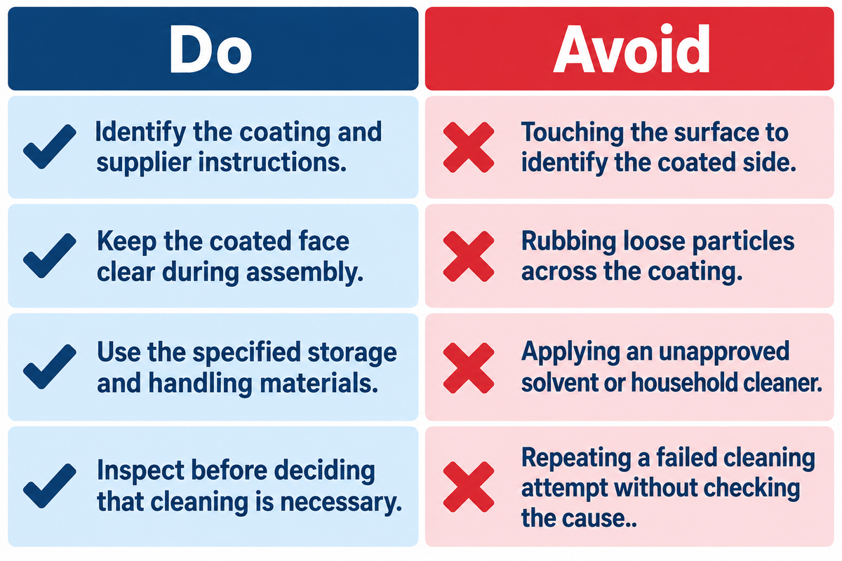
Cleaning the coated surface of a mirror or other reflective component should only be done with solvents and cleaning agents approved for that coating, and with care not to damage it. The coating should be identified before choosing a cleaning method, since protected surfaces and exposed metal films may require different treatment.
According to the Isaac Newton Group’s guidance on optical handling, “Never touch an optical surface”; handle the part at appropriate edges or supports. Household mirror-cleaning routines shouldn’t be applied automatically to exposed optical coatings.
Do
- Identify the coating and supplier instructions.
- Keep the coated face clear during assembly.
- Use the specified storage and handling materials.
- Inspect before deciding that cleaning is necessary.
Avoid
- Touching the surface to identify the coated side.
- Rubbing loose particles across the coating.
- Applying an unapproved solvent or household cleaner.
- Repeating a failed cleaning attempt without checking the cause.
What is the main disadvantage of a first surface mirror?
The major drawback of an exposed working coating is that it faces the environment and needs more careful handling. A protective overcoating can be provided, but doesn’t allow every cleaning method to be used. If continual contact can’t be avoided, look at modifying the enclosure/access and mirror specification.
Records of contamination and cleaning should include dates. A persistent mark may be coating damage rather than removable dirt, and further wiping may make it harder to diagnose. If this happens, return to the supplier and use their inspection procedure.
First Surface Mirror Price: What Changes the Quote
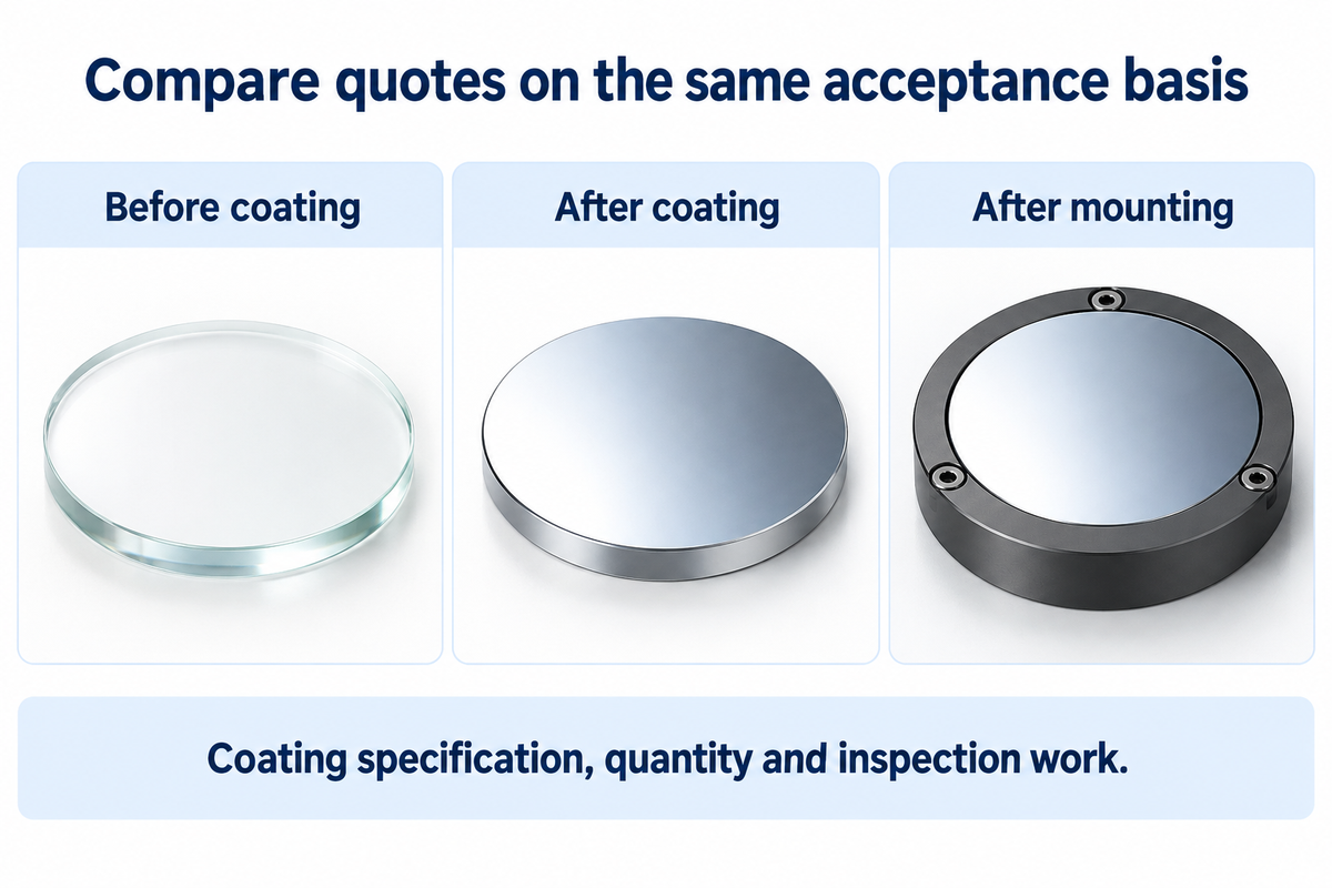
First surface mirror price reflects the finished coating specification, quantity, and inspection work. Fabrication isn’t independent of size and shape, while tightly coupled tolerances can add polishing and measurement steps to the process. Quotes must be compared on the same acceptance basis, including whether flatness is specified before coating, after coating, or after mounting.
Why are first surface mirrors so expensive?
Precision first surface mirrors can be expensive because the supplier must control and verify an exposed optical surface. The difficulty of simultaneously meeting tight requirements for thickness, wedge, and flatness is described in the authored Laser Focus World technical article by David Collier, Wayne Pantley, and David Kemp. A tolerance can be relaxed only when the instrument can accept the change.
Requirements for surface defects should be functionally justified. Kreischer’s abstract for an optical design conference identifies scratch-dig specifications as a cost driver and challenges overemphasis on them. Scratch-dig defects shouldn’t be ignored; rather, the inspection should be justified based on the actual performance of the instrument.
A cheaper quote may cover a different clear aperture, looser shape requirements or less testing. Optica identifies surface quality (scratch-dig) as a key cost factor. Compare price against a baseline with measurable requirements, with justified improvements priced separately. Avoid paying for “superior precision” without a measurable definition.
Choosing a First Surface Mirror Supplier
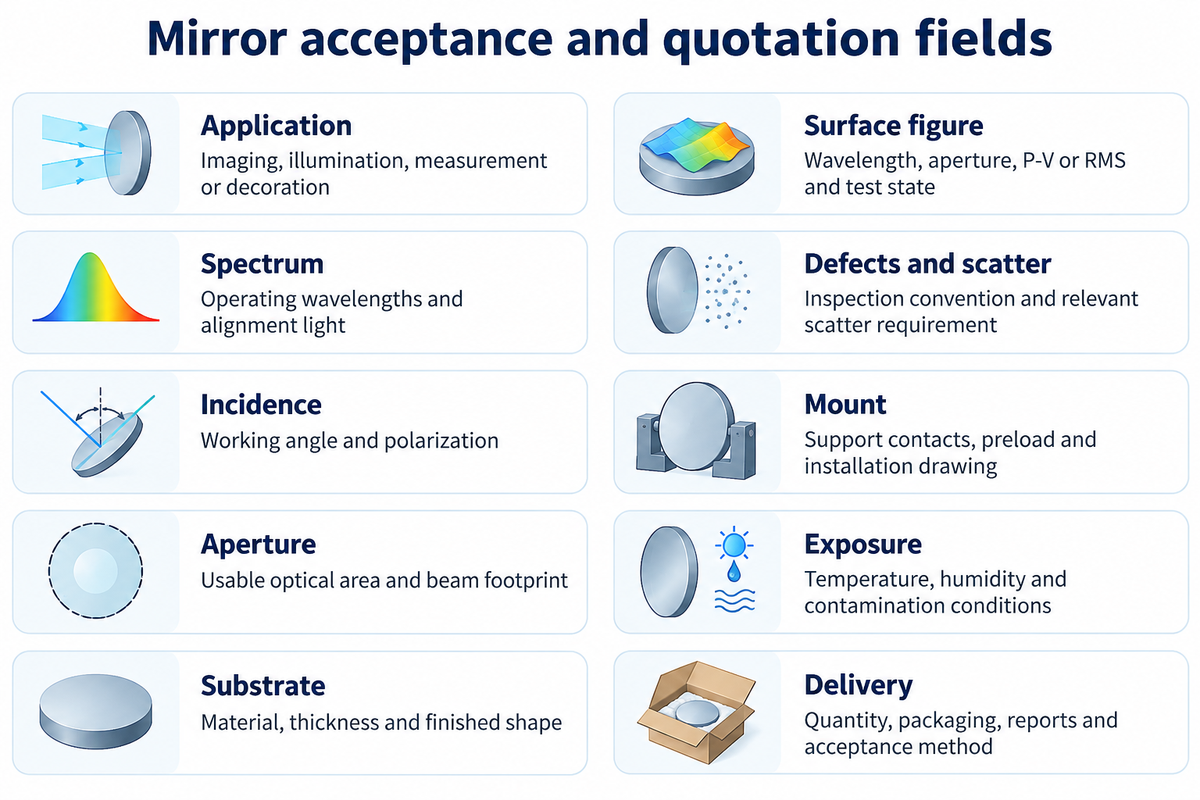
A supplier of first surface mirrors should be able to relate the drawing, coating curve, and inspection records to the delivered part. Include your intended optical condition and how the part will be mounted to the instrument in your request for quotation. Common quotation fields make differences visible, and give both parties the same acceptance basis.
| Field | What to provide or request | Why it changes the decision |
|---|---|---|
| Application | Imaging, illumination, measurement or decoration | Establishes the performance objective |
| Spectrum | Operating wavelengths and alignment light | Defines the useful coating band |
| Incidence | Working angle and polarization | Makes reflectance data comparable |
| Aperture | Usable optical area and beam footprint | Separates active area from nominal dimensions |
| Substrate | Material, thickness and finished shape | Connects optical and mechanical requirements |
| Surface figure | Wavelength, aperture, P-V or RMS and test state | Prevents comparison of unlike flatness claims |
| Defects and scatter | Inspection convention and relevant scatter requirement | Separates appearance from functional performance |
| Mount | Support contacts, preload and installation drawing | Defines the finished measurement condition |
| Exposure | Temperature, humidity and contamination conditions | Informs coating durability and enclosure choices |
| Delivery | Quantity, packaging, reports and acceptance method | Makes the commercial comparison complete |
ISO 9211-2:2024 addresses specification of coating optical properties. ISO 9211-3:2024 addresses environmental durability in relation to intended exposure. These offer relevant specification frameworks; the purchase order still needs to stipulate the agreed conditions and evidence.
Where can I buy the first surface mirror?
Purchase a first surface mirror from an optical component supplier that can document the coating and finished surface required for your application. Catalog parts, in general, suit a design that meets their published limits. For a custom inquiry, be sure to provide the acceptance criteria above, so the supplier can assess feasibility before promising performance.
For a project involving custom glass parts, SW Glass’s optical glass solutions offer a starting point for substrate and fabrication requirements. Also, ask for confirmation regarding the specific mirror coating, testing, and supply scope in the quotation.
Frequently Asked Questions
How are first surface mirrors made?
First surface mirrors are made by applying a reflective coating to a prepared front surface. The substrate is shaped and finished for the required optical geometry, then coated using a process suited to the selected materials. Protective or enhancement layers may be added. Assess final optical performance by inspecting the finished coated part rather than relying on substrate measurements alone. Ask which inspection results accompany the component you’ll receive.
Are first surface mirrors good?
Yes, first surface mirrors are good for applications that need to avoid reflection through a supporting glass plate. Their value depends on useful reflected power from the coating and image quality maintained by suitable surface figure and mounting. Judge these together by testing the chosen component in the intended enclosure before acceptance. An ordinary viewing mirror may still be sufficient when the extra reflection path doesn’t affect the task.
Which first surface mirror is best?
For general visible-light imaging, start with protected aluminum; consider protected silver when its specified band better meets the power budget. Start with the operating band and beam footprint, then define the required figure and defect limits. Consider the environment and cleaning access before choosing protection. Compare documented measurements under the same conditions. Include those conditions in the purchase order and inspection plan. Check the complete part in its intended mount before approving repeat orders.
Can I make a first surface mirror at home?
Yes, a DIY reflector can demonstrate front-surface geometry at home, but modifying a household mirror doesn’t ensure optical-grade performance. Removing paint or altering the backside may damage the coating. For imaging or measurement, use a finished component with documented acceptance data.
How do I cut a first surface mirror?
Order the mirror at its required finished size; any cutting and edge-finishing process must suit the specific substrate and coating. Cutting an already coated part can damage edges or contaminate the optical surface, so define the usable aperture after machining and require inspection before installation.
Discuss your glass component requirements
Send SW Glass your drawing, operating wavelength, usable aperture and mounting arrangement. Include the coating and inspection evidence you need so the available supply scope can be confirmed.
November 2026 Update. The throughput table illustrates calculated results, based on assumptions stated. Named coating examples belong to the cited supplier and aren’t SW Glass product specifications.
References & Sources
- Introduction to mirrors Florida State University, Molecular Expressions.
- Polarization documentation National Institute of Standards and Technology.
- ISO 10110-7:2017: Surface imperfections International Organization for Standardization.
- Optical Scattering of Surfaces National Institute of Standards and Technology.
- Mirror deformation versus contact area in mounted flat mirrors Clark, Penado and Cornelius, Arizona university research record.
- Optics cleaning and handling guidance Isaac Newton Group of Telescopes.
- Know the trade-offs when specifying mirrors Collier, Pantley and Kemp, Laser Focus World.
- The Adversarial Relationship between Optical Performance and Scratch-Dig Cody B. Kreischer, Optica conference abstract.
- ISO 9211-2:2024: Optical properties International Organization for Standardization.
- ISO 9211-3:2024: Environmental durability International Organization for Standardization.