Get in Touch with Saiweiglass


Dichroic Glass and Optical Filters: Thin-Film Interference Physics, Cutoff Specifications, and Custom Sourcing

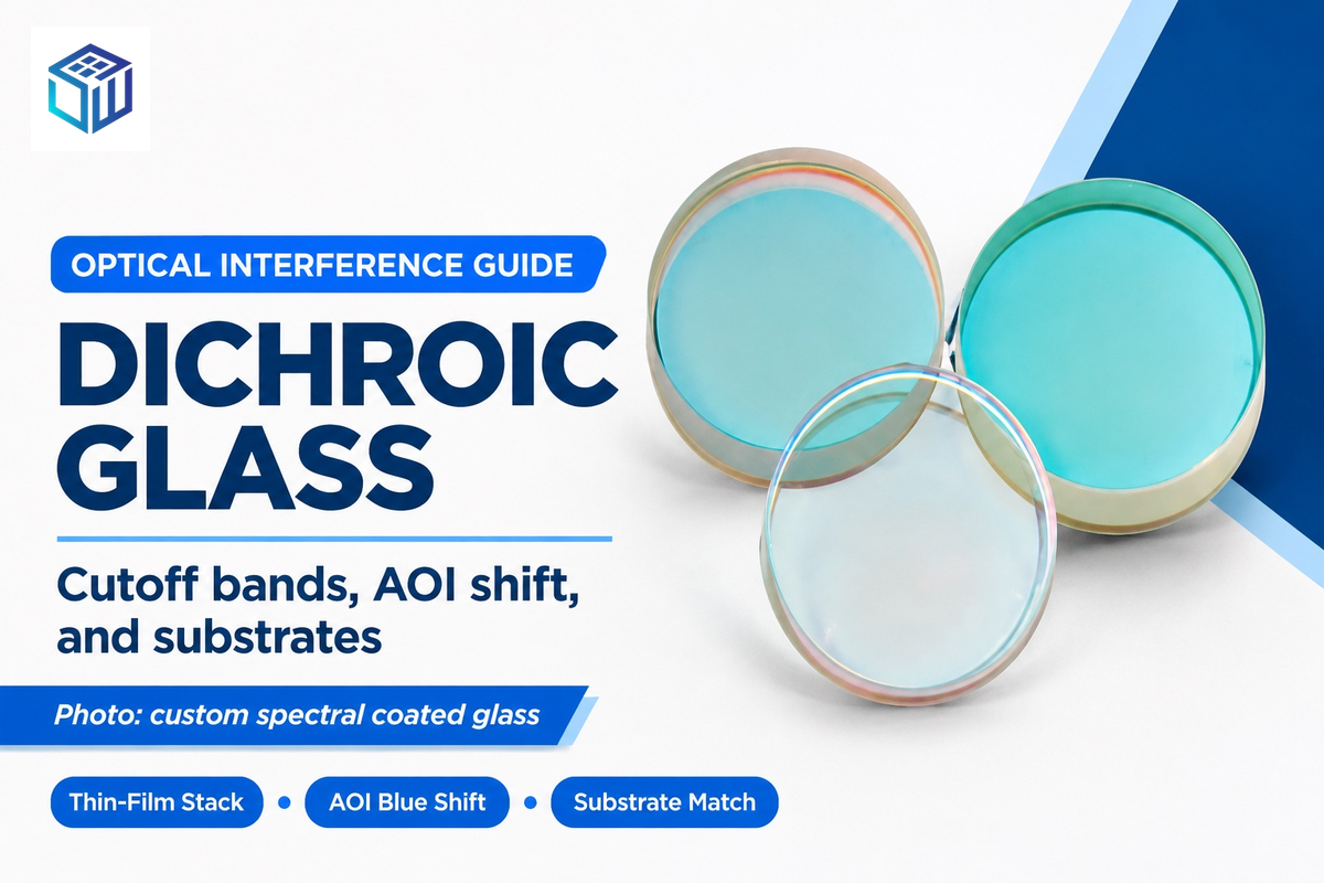
Dichroic optical glass is a specialty vacuum-coated optical glass component that can split light into two spectra using the phenomenon of thin-film interference. When engineered on precise custom optical glass substrates, the stack reflects targeted wavelength spectra with mirror-like efficiency. Simultaneously, it transmits the other spectra with low absorption in the coating material’s design band. Bulk-tinted glass and dyed polymer sheets trap the absorbed light as thermal energy. In comparison, layered high and low refractive index dielectric thin films change the color and cutoff edge as the viewing angle changes.
Optical engineers and architectural specifiers often experience unexpected spectral drift when moving from a datasheet to a live assembly. Tilting a standard interference stack from 0 degrees to 45 degrees shifts the cutoff wavelength toward the blue region. That tilt also splits s-polarized and p-polarized light edges. Meanwhile, exterior glazing purchasers need to discern true vacuum deposited metal oxide glasses from adhesive polymer films. Organic surface films and pressure-sensitive adhesives can degrade or peel at exposed edges due to prolonged exposure to ultraviolet radiation.
This engineering guide provides equations for estimating thin-film interference and the acceptable limits for cutoff wavelength. It outlines rules for angles of incidence and substrate flatness as well as batch economics for coating materials. The guide includes the 4-Band Dichroic Filter Cutoff & AOI Shift Worksheet for optical assemblies. The guide also provides the 5-Dimension Dichroic Glass vs Polymer Film Selection Matrix for architectural and lighting applications.
How dichroic thin-film interference splits transmitted and reflected wavelengths
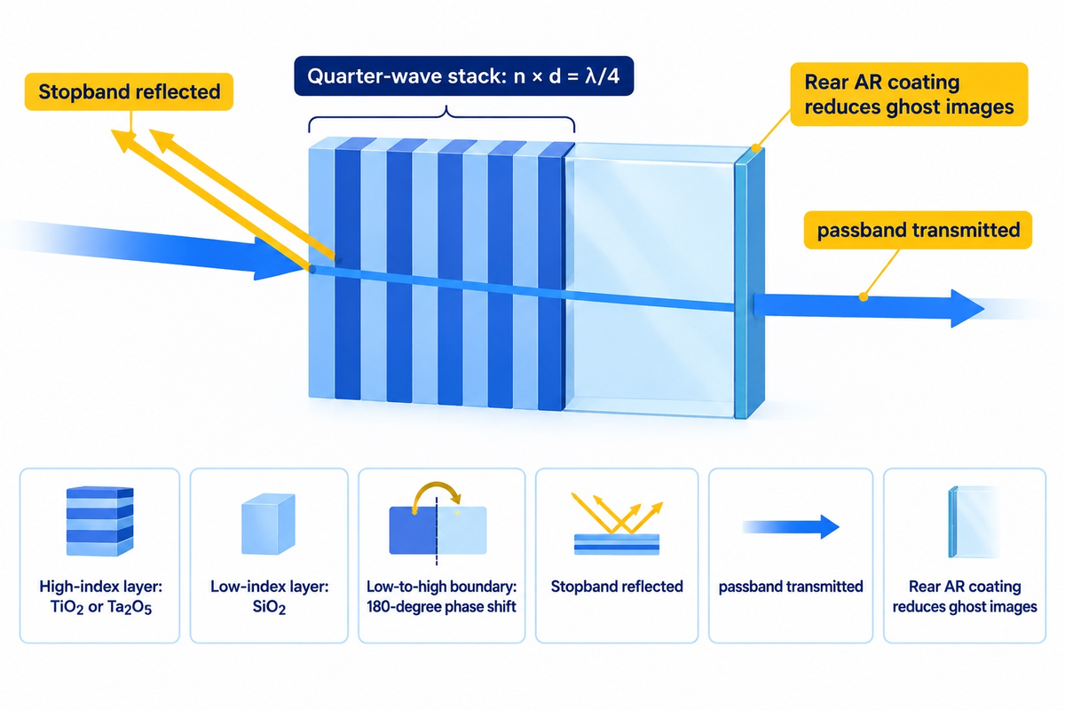
Modern dichroic filters rely on phase interference for their operation. According to the Florida State University National High Magnetic Field Laboratory, a quarter-wave stack reflector alternates high-index and low-index dielectric materials, deposited to one-quarter of the target design wavelength (n × d = λ/4).
Wavelengths of light strike a boundary moving from a low-index film to a high-index film. At that interface, the reflected ray suffers a 180-degree phase shift. Reflections at a high- to low-index boundary cause zero phase shift. Reflections of certain wavelengths across dozens of interfaces coincide in phase. They combine to produce high stopband reflectance. Outside that stopband, the reflected waves cancel out. This allows the complementary passband to transmit through the glass substrate.
In visible and near-infrared optics above 400 nm, common high-index layers include titanium dioxide (TiO2, typical visible index n ≈ 2.35 to 2.40 depending on wavelength and deposition) or tantalum pentoxide (Ta2O5, typical visible index n ≈ 2.10). Coaters pair those layers with low-index silicon dioxide (SiO2, n ≈ 1.46). As documented in NIH PubMed Central thin-film coating research, these metal oxide stacks exhibit near-zero absorption in the visible band. Below 380 nm in the ultraviolet range, TiO2 begins absorbing optical energy. For UV channels, engineers switch to wide-bandgap hafnium oxide (HfO2) or aluminum oxide (Al2O3) paired with SiO2 or magnesium fluoride (MgF2) on UV fused silica.
This multilayer interference effect is different from the other two definitions of dichroism. In crystal optics, anisotropic minerals like tourmaline absorb one polarization state more than the other. In historic glassmaking, colloidal gold and silver nanoparticles dispersed inside molten glass scatter green light while transmitting ruby red. The Lycurgus Cup is an example of this nanoparticle effect. Now, industrial dichroic glass comes from a different technology: vacuum deposition research conducted by NASA and aerospace optics. The goal was to produce durable, thin-film reflectors for astronauts’ visors and satellite sensors.
To decrease Fresnel reflection loss at the second surface, optical precision windows pair a front interference stack with anti-reflective (AR) surface coatings for display glass on the rear face. Adding a rear AR surface stack reduces ghost images caused by reflections from the glass surface, and increases net passband transmission in the target wavelength range.
Specify cutoff wavelength tolerance, angle of incidence shift, and substrate flatness
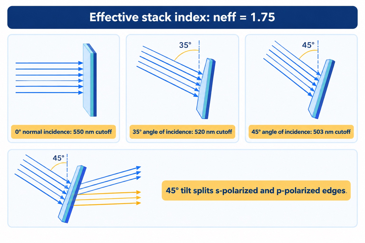
Specifying a dichroic filter or mirror requires defining the nominal cutoff wavelength tolerance and angle-of-incidence blue shift. Engineers must also manage s- and p- polarized edge splitting at oblique angles, as well as substrate stiffness against coating stress. When unpolarized beams strike a 45-degree mirror, engineers specify thin-film stacks to compensate for the s/p transition.
How does angle of incidence shift the cutoff wavelength of a dichroic filter?
Tilting a dichroic filter or mirror away from normal incidence (0 degrees) toward 45 degrees shifts the cutoff toward shorter wavelength (blue shift). This happens because tilting a mirror shortens the effective path difference (optical) in the dielectric layers. At 45 degrees AOI, s-polarized light and p-polarized light reflect differently, which results in an edge splitting of the cutoff. This splits the cutoff edge into two curves unless the stack is engineered for 45-degree polarization compensation.
For collimated light at moderate tilt angles, engineers can calculate the shift in wavelength (λ at angle θ) using the effective refractive index (neff) of the stack.
λ(θ) = λ0 × √[1 − (sin θ / neff)²]
Here, λ0 is the half-maximum cutoff wavelength at normal incidence (i.e. AOI = 0°), and θ is the angle of incidence in air. The effective index of the stack neff typically varies from 1.65 to 1.95, depending on the ratio of the SiO2 to TiO2 or Ta2O5 layers. With a 550 nm half-maximum cutoff at normal incidence and an effective index of 1.75, the calculated cutoff is around 520 nm at a 35° angle of incidence and 503 nm at a 45° angle of incidence. Due to this effect, the coated surface appears to change color depending on the angle of observation.
According to Alluxa’s angle-of-incidence and polarization specification guide, polarization splitting becomes pronounced at non-zero angles of incidence. In a 45 degree tilted quarter-wave stack, the p-polarized reflection band becomes narrower and the s-polarized reflection band becomes wider. Depending on the index contrast and design of the stack, the split between the s-polarized and p-polarized cutoff edges widens at larger tilt angles, creating a stepped transmission transition in unpolarized light.
In addition, during system layout, engineers must take into account three other optical effects:
- Cone-angle effect and field spread impact non-collimated beams. In a converging or a diverging beam, a filter is exposed to a range of incident angles set by the local cone of the beam and field spread. However, in a collimated beam, a filter can receive a narrow angular range even with a high NA objective.
- Phase retardance due to polarization occurs with oblique reflections. Even when the intensities of the s- and p-polarizations are matched, for example with a 45-degree dichroic mirror, there will be differential phase delay across the transition zone. Interferometric and ellipsometric techniques therefore require phase-control stack designs.
- Reflected wavefront quality is impacted by substrate thickness and coating stress bow. Dense plasma and ion-assisted coatings generate thin films under compression. Thin substrates can bow under compressive film stress. Stiffness of the substrate, along with thickness, compressive stress, the clear aperture, and how it’s mounted, all impact the distortion of the reflected wavefront. According to Alluxa’s hard-coated thin-film filter white paper, commercial cutoff tolerances for thin-films fall into three tiers: High Performance, Standard, and Lowest Cost.
| Filter Category & Spectral Band | Nominal 0° Cutoff (λ0) | 15° AOI Shifted Cutoff | 30° AOI Shifted Cutoff | 45° AOI Estimated Cutoff (neff = 1.75; scalar approximation) | 45° Polarization Design Requirement | Illustrative Standard Tolerance Tier | Typical Substrate Option |
|---|---|---|---|---|---|---|---|
| Band 1A: UV-Violet Laser Longpass | 405 nm | 401 nm | 388 nm | 370 nm | Specify s/p-compensated stack for 45° unpolarized beams | ±8.1 nm | 2.0 mm UV fused silica |
| Band 1B: Blue Laser Beam Combiner | 450 nm | 445 nm | 431 nm | 412 nm | Specify s/p-compensated stack for 45° unpolarized beams | ±9.0 nm | 2.0 mm UV fused silica |
| Band 2A: Blue-Green Beam Splitter | 490 nm | 485 nm | 470 nm | 448 nm | Specify s/p-compensated stack for 45° unpolarized beams | ±9.8 nm | 2.0 mm Borofloat / fused silica |
| Band 2B: Green Harmonic Separator | 532 nm | 526 nm | 510 nm | 487 nm | Laser-line s-pol or p-pol specific design | ±10.6 nm | 2.0 mm UV fused silica |
| Band 3A: Green-Red Fluorescence Dichroic | 550 nm | 544 nm | 527 nm | 503 nm | Specify low-splitting 45° fluorescence cube stack | ±11.0 nm | 2.0 mm Borofloat / fused silica |
| Band 3B: Orange-Red Machine Vision Splitter | 600 nm | 593 nm | 575 nm | 549 nm | Specify s/p-compensated stack for wide-cone lenses | ±12.0 nm | 1.1 to 2.0 mm Borofloat 33 |
| Band 4A: Red-NIR Biophotonics Dichroic | 650 nm | 643 nm | 623 nm | 595 nm | Specify phase- and polarization-controlled stack | ±13.0 nm | 2.0 mm Borofloat / fused silica |
| Band 4B: Visible-NIR Hot Mirror Cutoff | 700 nm | 692 nm | 671 nm | 640 nm | Obtain coating-specific 45° s/p curve for thermal rejection | ±14.0 nm | 1.1 to 2.0 mm borosilicate |
Compare dielectric dichroic coating stacks against absorptive colored glass filters
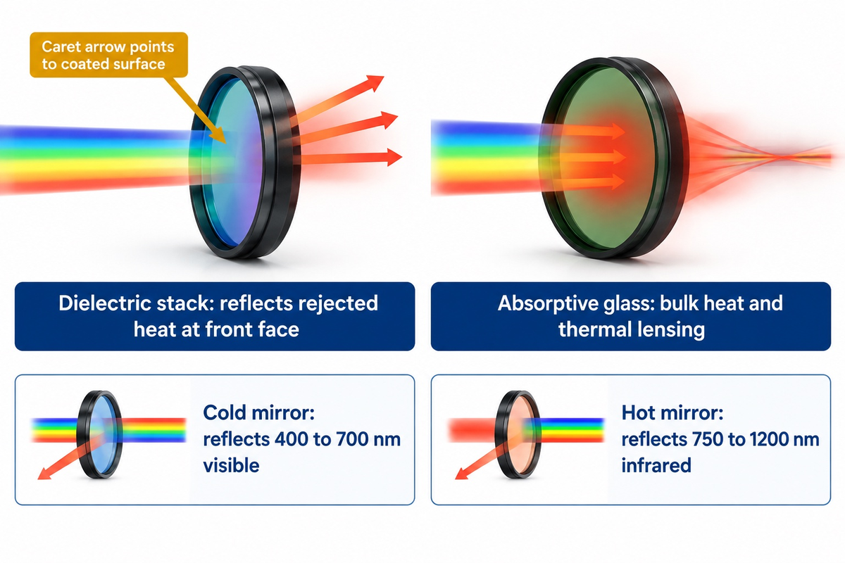
Colored filter glass, as compared to a thin-film substrate stack, absorbs the out-of-band photons, resulting in thermal heat build-up in the glass.
What is the difference between a beam splitter and a dichroic mirror?
A general beam splitter partitions an incident optical beam into two paths based on intensity or polarization. On the other hand, dichroic mirrors partition by spectral range. They reflect a specific wavelength range and transmit the rest with low absorption loss.
As detailed in Photonics Media’s life science optical filter comparison, absorptive colored glass filters rely on ionic dopants or colloidal compounds melted into the glass batch. When colored glass absorbs rejected wavelengths under high incident power and limited heat dissipation, the absorbed energy heats the glass bulk. Absorbed power can produce thermal lensing, and severe temperature gradients or constrained thermal expansion can fracture the glass. Some absorptive glasses emit fluorescence when excited, increasing background when that emission falls within the microscope’s detection band.
In comparing absorptive colored glasses to interference stacks, colored glasses exhibit a lower angular wavelength shift. When an absorptive filter is tilted, the path length through the glass is increased, as is the reflection and polarization response. Absorptive bands don’t exhibit a blue shift as do interference bands, though a cutoff can be set at a defined transmission level and move. When a deep blocking filter with no blue shift is required, the optical designers usually employ a combination of dichroic coating (dielectric) and an absorptive glass.
When installing dichroic filters or hybrid assemblies, physical orientation matters. As noted in Photonics Media’s optical filter orientation analysis, filter orientation dictates system effectiveness, and the dielectric coated surface should face the incoming light. In ringed filters, the caret arrow on the anodized mount of the filter should point to the coated surface of the filter. Mounting the coated side toward the lamp or laser reflects rejected heat immediately before it enters the glass base.
Two high-volume industrial variants illustrate this thermal management principle:
- Cold mirror stacks efficiently reflect visible light (400 nm to 700 nm) and transmit infrared heat wavelengths (>750 nm) out the rear of projector and stage lighting housings.
- Hot mirror coatings transmit visible light while reflecting infrared radiation (750 nm to 1200 nm) to protect CMOS imaging sensors, industrial touchscreens, and outdoor LCD enclosures from solar thermal loading.
| Specification & Comparison Benchmark | Hard-Coated Sputtered / IAD Dichroic | Conventional E-Beam Soft Dichroic | Absorptive Colored Glass Filter |
|---|---|---|---|
| Primary Filtering Mechanism | Multi-layer thin-film phase interference | Multi-layer thin-film phase interference | Bulk ionic or colloidal dopant absorption |
| Passband Transmission Profile | High in design band when paired with rear AR coating | Moderate to high in design band | Thickness-dependent (governed by Beer-Lambert absorption) |
| Transition Edge Slope | Steep transition between passband and stopband | Moderate transition slope | Broad and gradual transition across tens of nanometers |
| Rejected Light Handling | Reflected (low absorption within operating band) | Reflected (low absorption within operating band) | Absorbed as bulk heat (thermal lensing risk at high flux) |
| Angle of Incidence (AOI) Sensitivity | High (interference blue shift at higher tilt angles) | High (interference blue shift plus humidity drift) | No interference blue shift (path-length and Fresnel changes) |
| Humidity & Environmental Stability | Dense oxide microstructure reduces moisture penetration and spectral drift | Porous film structure (susceptible to upward moisture wavelength shift) | Bulk glass matrix unaffected by ambient humidity |
| Fluorescence Background in Low-Light Imaging | Depends on substrate purity, coating materials, and excitation band | Depends on substrate purity and optical cement selection | Some absorptive glasses emit fluorescence when excited in the detection band |
| Durability Test Specification | Specify humidity, thermal-cycling, and adhesion tests with acceptance limits | Requires protective lamination or sealed housing | Governed by base flat-glass durability (ASTM C1036-25) |
Compare vacuum-deposited dichroic glass against polymeric color-shifting window film
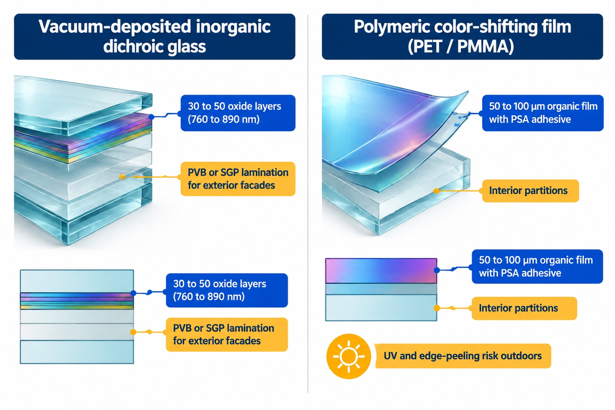
In modern architecture, specifiers have to differentiate inorganic vacuum-coated architectural glass from adhesive polymeric color-shifting window films. Both materials exhibit an iridescent, color-shifting effect, which displays different colors in transmission and reflection. Their differences in material lifespan, structural ratings and failure modes are significant.
Glass Magazine’s technical guide to dichroic glass states that architectural and decorative vacuum-deposited dichroic glass typically stacks 30 to 50 layers of metal oxides. Even though it can be made of up to 50 individual thin layers, the total coating thickness is only 30 to 35 millionths of an inch (760 nm to 890 nm). Multi-cavity optical beam splitters for use in scientific instruments can be made with 50 to 100 individual thin layers. Stacks of that type of beam splitters have a physical thickness of 3 to 8 micrometers.
Micro-thin layers of metal oxides, which include inorganic ceramic films such as quartz crystals (SiO2) and titanium or chromium oxides, are bonded directly to the glass surface in a vacuum chamber. Therefore, they’re immune to polymer chain scissions caused by ultraviolet radiation. When laminated between two lites of clear glass or low iron glass using an interlayer of polyvinyl butyral (PVB) or ionoplast (SGP), vacuum coated glass panels are stable for decades in the face of solar ultraviolet radiation.
Polymeric color shifting films consist of co-extruded organic polyester and acrylic layers. Sheets are adhered to an existing glazing using pressure sensitive adhesive (PSA). They’re ideally suited for quick, low cost, interior partitions for retail or seasonal art installations. However, they’re poorly suited for exterior curtain walls, skylights, and luminaires. Organic polymer films undergo edge peeling and surface scratching from long term solar ultraviolet exposure.
When specifying architectural coated glass, it is important that engineers consult the correct ASTM standards. ASTM C1036-25 (Standard Specification for Flat Glass) covers the quality, thickness tolerances and point blemish limits of flat glass substrate. ASTM C1376, on the other hand, covers pyrolytic and vacuum-deposition coatings on flat glass and ASTM C1172 covers integrity of laminated architectural flat glass assemblies. If architectural panels require safety strengthening, refer to the thermal tempering process for safety glass panels. Coatings that cannot withstand tempering are deposited after heat treatment; heat-treatable coatings can be deposited before it. Heat-strengthened plies can subsequently be laminated.
| Evaluation Dimension | Vacuum-Deposited Inorganic Dichroic Glass | Polymeric Color-Shifting Window Film (PET / PMMA) |
|---|---|---|
| 1. Coating Composition & Thickness | 30 to 50 inorganic metal-oxide thin layers (~760 to 890 nm; up to 3–8 μm in precision optics) | Co-extruded organic polymer multilayer film (50 to 100 μm) with acrylic PSA adhesive |
| 2. Thermal & Heat-Source Stability | Inorganic oxide layers tolerate elevated luminaire temperatures (assembly limit set by substrate and interlayer) | Organic polyester and PSA adhesive soften, shrink, or outgas near high-wattage heat sources |
| 3. UV & Exterior Weathering Behavior | Inorganic metal oxides resist UV yellowing; laminated with PVB or SGP interlayers for exterior facades | Organic adhesive and polyester layers are susceptible to UV degradation and edge peeling in exterior exposure |
| 4. Surface Hardness & Abrasion Resistance | Hard oxide ceramic surface | Polymeric surface susceptible to scratching |
| 5. Fabrication & Lamination Compatibility | Supports CNC edging, hole drilling, and PVB/SGP autoclave lamination into safety glass panels | Surface-applied sheet roll; can trap bubbles or peel at exposed wet-glazed edges |
Select vacuum deposition methods and base substrates for custom glass products
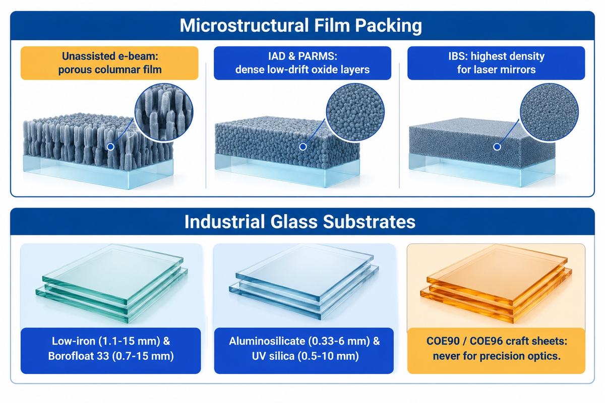
Not all vacuum-deposited dichroic coatings perform equally in humid and thermally cycled environments. The physical deposition method inside the vacuum chamber dictates the film’s microstructural packing density and spectral stability. The right combination of energetic coatings and glass substrate can eliminate field wavelength drift and thermal breakage.
Conventional electron beam (e-beam) evaporation heats metal oxide source material in vacuum, and as noted in Omega Optical’s thin-film environmental durability engineering guide, porous thin-film structures remain sensitive to environmental moisture. The resulting vapor condenses onto rotating substrates. As the molecules reach the substrate with low kinetic energy, the film grows in a porous columnar structure. When ambient humidity rises, water vapor penetrates those microscopic pores. That moisture alters the effective refractive index, reduces transmission, and shifts the filter’s cutoff wavelength upward.
Modern coaters use energetic processes noted in ElectroOptics’ 2026 optical coating technology review to reduce moisture drift in industrial sensors and outdoor displays.
- With Ion-Assisted Deposition (IAD), energetic argon or oxygen ions bombard the growing film in e-beam evaporation and densify thin layers of metal oxides. This process reduces moisture drift compared to unassisted e-beam evaporation.
- Plasma-Assisted Reactive Magnetron Sputtering (PARMS) is used to sputter a metal or sub-oxide target in a reactive oxygen plasma. Hard sputtered coatings achieve dense microstructure and exhibit low moisture drift.
- Ion-Beam Sputtering (IBS) achieves the highest film density for ultra-narrowband laser mirrors, but is slower compared to other deposition methods and increases the cost of the sputtering chamber.
Deposition cycle matching is as critical as choosing the correct type of glass. Industrial optical and display engineers select from four primary glass types based on the transmission spectrum and thermal expansion. Aligning substrate refractive index, dispersion, and thermal limits with the coating stack is explained in substrate dispersion and thermal limits across optical glasses.
- For budget base glass applications in architectural glass panels, smart mirrors, and display covers, commercial glaziers use ultra-clear low-iron soda-lime glass (1.1 mm to 15 mm). Compared with standard float glass, choosing low-iron extra-clear glass rather than standard soda-lime glass will reduce green tints and improve color fidelity.
- Borosilicate glass (Schott Borofloat 33 / Pyrex, 0.7 mm to 15 mm) provides a low coefficient of thermal expansion (CTE ≈ 3.25 × 10⁻⁶ /K) and high thermal shock resistance for cold mirrors, hot mirrors, and medical lighting filters.
- Toughened aluminosilicate glass (0.33 mm to 6 mm) is used for tough, chemically strengthened solid glass for rugged touchscreens, handheld optical scanners, and other optical windows.
- UV grade fused silica (0.5 mm to 10 mm) offers ultra-pure synthetic SiO2 with deep-UV transmission down to 185 nm and near-zero thermal expansion for laser and fluorescence dichroic filters.
In contrast, studio artisans and stained glass artists use specially engineered kiln-compatible sheets of art glass designed for glass fusing. Craftspeople often fuse a piece of dichroic glass in a kiln for a glass art project or a jewelry project. When firing fused glass cabochons, a pendant, or dichroic glass jewelry, glass layers must have similar thermal expansion and viscosity behavior throughout the firing and annealing cycle. Craft suppliers produce COE90 glass and COE96 glass in smooth clear or black glass bases. They also produce textured glass, crinklized dichroic, and etched dichroic patterns and sheets. In addition, fused dichroic craft sheets are optimal for kiln glass art. However, for B2B customers, COE90 or COE96 glass pieces must never be used in place of precision optical components.
Verify optical spectrum uniformity, environmental durability, and surface quality
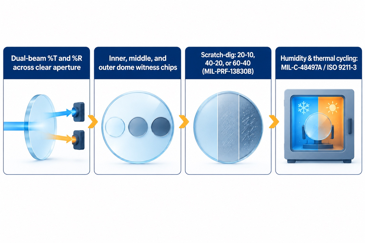
Incoming quality control for high-quality dichroic glass and custom optical filters requires verification of three measurable dimensions across lots. Quality inspectors evaluate uniformity of spectral cutoff across the clear aperture, surface quality of cosmetic scratches and digs, and adhesion durability against humidity and thermal cycling.
Does vacuum-deposited dichroic glass fade or delaminate over time?
Inorganic metal-oxide interference layers resist ultraviolet yellowing far better than organic dyes, though extreme UV or solarization can still alter long-term transmission. Delamination can result from interface contamination, poor adhesion, coating stress, moisture, thermal shock, or chemical attack. Dense sputtered and ion-assisted dichroic coatings reduce moisture penetration and spectral drift compared with porous evaporated coatings. SW Glass tests cover-glass coatings per MIL-C-48497A and ISO 9211-3; stack acceptance follows its qualification report.
Four verification protocols need to be applied on production batches to prevent field failures and assembly rejects by engineering teams.
- Dual beam spectrophotometry should be used to check for uniformity of center to edge transmission. It’s important to also check the reflectivity of the optic (%R) and the transmission of the optic (%T) at the AOI, at multiple locations on the clear aperture. To evaluate coating uniformity, witness chips from the inner, middle and outer radii of the dome should be inspected.
- Cosmetic scratch-dig inspection verifies surface quality per MIL-PRF-13830B and ISO 10110-7:2017 surface imperfection standards. Laser and fluorescence imaging optics commonly require 20-10 or 40-20 scratch-dig. Machine vision windows use 40-20 or 60-40, and architectural display panels follow ASTM C1036-25 and C1376 visual criteria.
- Environmental durability conditioning validates film adhesion. Specify humidity, thermal-cycling, and adhesion tests for the selected hard coating under MIL-C-48497A and ISO 9211-3 protocols, with explicit acceptance limits for delamination and spectral shift.
- Protect coated faces during fabrication and cleaning. Schedule CNC cutting, edge grinding, beveling, drilling, and strengthening before vacuum deposition. When pre-coated dichroic glass sheets have to be cut after coating, cover the coated glass surface with a removable polymer strip-coat to prevent slurry scratches.
Evaluate batch chamber economics, unit pricing drivers, and lead times for custom dichroic optics
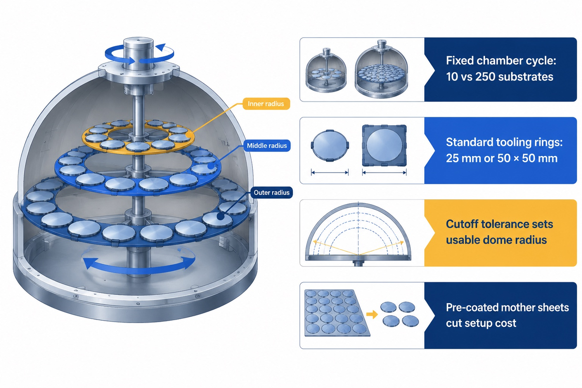
Unlike stamped metal brackets, where unit cost drops linearly with order quantity, vacuum-deposited optical coatings follow step-function chamber economics. Custom dichroic glass and optical filters vary with the substrate, dimensions, layer counts, and spectral tolerance. Therefore, unit prices are quoted project by project and don’t appear on a catalog. Aligning order quantities with planetary rotation dome capacity significantly reduces per-piece coating cost.
Vacuum coating requires chamber pump-down and controlled deposition. Some methods for thickness control of evaporated optical coatings include the use of quartz crystals or optical monitors. Whether the chamber holds 10 substrates or 250, cycle time and labor remain the same.
Four engineering decisions dominate unit pricing and lead time:
- How many parts can be loaded per run is determined by chamber dome fill factor and part geometry. Circular and rectangular filter blanks (25 mm diameter, 50 × 50 mm) readily load into tooling rings. Irregular or oversized profiles require aluminum shadow masks.
- Wavelength cutoff tolerance has a large effect on yield across the dome radius. Alluxa’s specification benchmarks illustrate that, for a non-critical cutoff tolerance, the coater can reduce cost and use full dome radii without center-only masking by going from High Performance to Standard or Lowest Cost.
- The tradeoff between the number of layers and luminous throughput affects cycle time. Steepening the transition by increasing filter cavities increases the slope of the tradeoff curve. As illustrated in the Evident Scientific Microscopy Resource Center, over-specification of attenuation and cavity counts can increase passband ripple and reduce luminous throughput in low light systems.
- Using a pre-coated mother sheet decreases the time and cost of setting up a chamber. Custom geometries can be sliced from pre-coated dichroic glass sheets for display windows, lighting lenses and decorative panels.
Qualify a custom dichroic glass and optical coating manufacturer for display and instrument builds
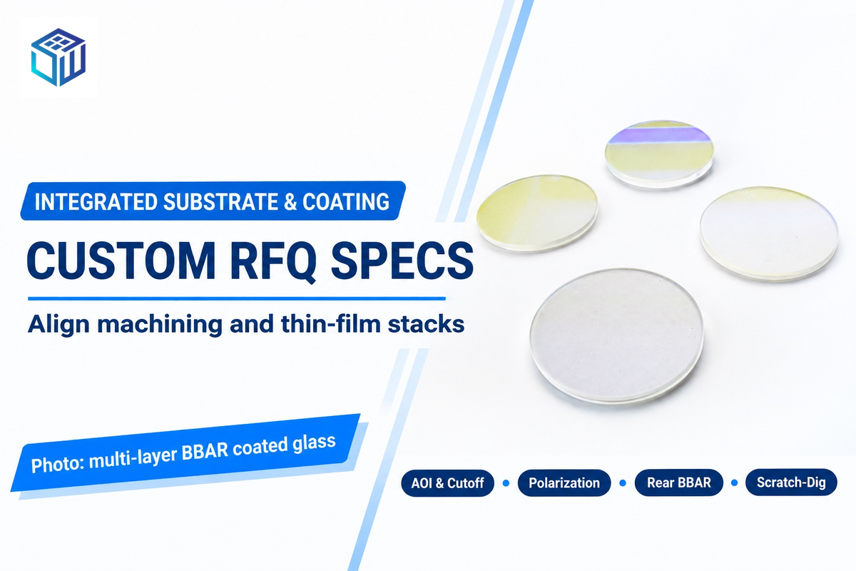
Gaps in accountability occur when sourcing dichroic optics from multiple raw-glass cutters and vacuum coaters. Companies such as Edmund Optics, Thorlabs, Semrock (IDEX), and Chroma Technology provide ready-to-sell scientific fluorescence filters and laser mirrors. Schott (Narima) and Prinz Optics specialize in large-format facade and decorative glazing. For custom OEM geometries, an integrated manufacturer brings machining and coating tolerances under one supplier’s control, and the combined effect remains part of the finished component’s tolerance budget.
At SW Glass (Dongguan Saiwei Glass Co., Ltd.), we combine in-house substrate machining with magnetron sputtering optical coating under ISO 9001:2015 quality management. Engineers sourcing custom display cover glass fabrication can specify substrates from 0.33 mm to 15 mm thickness across ultra-clear low-iron glass, Borofloat 33 borosilicate, aluminosilicate, Gorilla Glass, and fused silica. Our CNC machining centers hold +/-0.05 mm dimensional tolerances. We pair that machining with Class 1000 cleanroom AR/AF cover-glass coating tested per MIL-C-48497A, ISO 9211-3, and MIL-PRF-13830B. For custom AR-coated cover glass, standard minimum order quantity (MOQ) is 100 pieces, while custom spectral stacks are quoted to drawing specifications. We deliver custom prototypes in 3 to 5 days and complete mass production in 7 to 15 days.
Prior to releasing drawings for quotations, use the coated-side and dimensional callout rules for glass drawings and dichroic specification checkpoints below. Prior-art disclosures such as US Patent US11815705B2 on laser-damage performance in multi-layer dielectric coatings and US Patent US5135812A on symmetrical optically variable thin-film stacks illustrate how stack architecture varies by application.
- Substrate material and thickness: Specify Borofloat 33, fused silica, aluminosilicate, or low-iron glass, plus thickness (0.33 mm to 15 mm) and flatness limits.
- State the range of the spectral band and half-maximum cutoff wavelength, the reflectance of the stopband (%) or the optical density and specify the required tolerance.
- Operating angle of incidence (AOI) and cone half-angle: Define exact tilt angle (0°, 15°, 30°, or 45°) and whether the beam is collimated or converging.
- Polarization state: Specify random/unpolarized, s-polarized, p-polarized, or low-polarization-splitting stack requirements.
- Second-surface treatment and edge finish: Rear broadband AR, C-edge or bevel machining (+/- 0.05 mm), and coated side marking are to be indicated.
- Environmental and cosmetic acceptance standards: Call out scratch-dig grade (60-40, 40-20, or 20-10 per MIL-PRF-13830B) and durability test requirements (ISO 9211-3 / MIL-C-48497A).
Frequently asked questions
How do you pronounce dichroic and what does it mean in optics?
“Dy-KROH-ik.” The Greek roots of dichroic mean “two colored” or “made of two colors.” In manufacturing, like specialty glass, a dichroic filter or mirror splits an incoming light beam into two distinct wavelength bands. One spectral range passes through the substrate while the other is reflected. Absorption remains low within the coating materials’ intended operating band.
How can you tell which side of dichroic glass carries the thin-film coating?
The coated side is the side that reflects a bright mirror image when a gloved fingernail (or a wooden toothpick) is placed against it, with no gap, under white light. Keep the glass sheet/optical filter at a 45-degree angle to see this contact point. On the uncoated side, the reflection on the coated side appears as a separated mirror, with the gap varying with the substrate’s thickness, the refractive index, and the angle of observation.
Are GU10 and MR16 halogen or LED reflector bulbs made with dichroic glass?
Many commercial GU10 and MR16 spotlight reflector cups use a multi-layer cold-mirror dichroic coating deposited on the curved borosilicate glass reflector. This stack reflects visible light (400 to 700 nanometers) forward into the illumination beam. It allows infrared heat wavelengths (above 750 nanometers) to pass through the back of the lamp housing, thus keeping retail displays, artwork, and heat-sensitive food counters cool.
Is dichroic glass food safe and stable in kiln fusing?
A clear glass cap seals the dichroic coating during firing. Food-contact use requires the coating to be on chemically suitable glass and the food-contact surface to remain intact under the intended conditions of use. Exposed uncapped coatings should be on decorative surfaces.
What specifications should engineers include on an RFQ drawing for custom dichroic glass or optical filters?
Engineers should provide the type of substrate (i.e. Borofloat 33, UV-fused silica, and/or low-iron soda-lime glass) and the overall size when requesting a quote. Thickness tolerances, the half-maximum cut-on/cutoff wavelength, and allowable nanometer tolerances must be included. The operating angle of incidence, cone half-angle of the beam, state of polarization, passband transmission range, and stopband optical density must be stated in the request. Finally, call out scratch-dig surface quality per MIL-PRF-13830B and rear anti-reflective coating requirements.
References & Sources
- Florida State University National High Magnetic Field Laboratory Introduction to Interference Filters and Thin-Film Dichroic Mirrors
- University of Arizona College of Optical Sciences – Optical Thin-Film Interference and Dichroic Beam Splitters (Chapter 20)
- NIH PubMed Central (PMC7830637) – Refractive Index Contrast and Spectral Selectivity in Multilayer Dielectric Oxide Coatings
- Alluxa Optical Engineering Guide – Angle of Incidence (AOI) Shift and S/P Polarization Splitting in Thin-Film Filters
- Alluxa Technical White Paper – Specifying Plasma-Deposited Hard-Coated Optical Thin-Film Filters
- Omega Optical Engineering Note Thermal and Environmental Durability of Optical Thin-Film Coatings
- Photonics Media Selecting Color Filter Glass vs. Dielectric Interference Coatings for Life Science
- Photonics Media Engineering Article — Optical Filter Orientation Dictates System Effectiveness
- National Glass Association / Glass Magazine Dichroic Glass and How It Works in Architectural Glazing
- ASTM International ASTM C1036-25 Standard Specification for Flat Glass (2025 Revision)
- EKSMA Optics Technical Reference MIL-PRF-13830B and ISO 10110-7:2017 Optical Surface Quality Scratch-Dig Standards
- Evident Scientific Microscopy Resource Center Confocal Interference Filter Attenuation vs Luminous Throughput Trade-Offs
- ElectroOptics Industry Review Latest Sputtered and Ion-Assisted Optical Coatings for 2026 Photonics
- United States Patent and Trademark Office (Google Patents) — US11815705B2 Techniques for Improving Laser Damage Performance in Multi-Layer Dielectric Coatings & US5135812A Optically Variable Thin Film Flake and Collection of the Same
Related Posts
Trending now