Get in Touch with Saiweiglass



A display cover glass tolerance stack evaluates allowed dimensional variations of an assembled display. A panel can pass its own drawing and still foul the housing, conceal pixels or consume rear clearance. Start with physical endpoints, then separate glass dimensions, printed-feature location and assembly placement before adding any tolerances.
Updated October 2026
Cover glass for OEM industrial displays requires a chain that the component supplier, module supplier and assembler can confirm.
A display cover glass tolerance stack links housing, glass and display datums. Check perimeter clearance, installed depth and window alignment separately. Use adverse drawing limits for a limit check; measured process data need a justified statistical model.
Key takeaways
- A supplied module can already contain the cover: adding another cover thickness counts the same layer twice.
- In the hypothetical depth example, the four-term calculation leaves 0.44 mm minimum clearance before additional form or pose allowances.
- The illustrative printed-window budget leaves 0.25 mm on one edge before rotation, viewing and environmental checks.
- A smaller statistical spread doesn’t guarantee that every assembly allowed by the drawings fits.
Quick Specs: what the drawing check must define
- Fit: opening and finished outline, plus the locating scheme.
- Depth: reference planes, delivered module boundary and installed bondline.
- Window: printed edge, active-image edge and relative placement on each side.
- Acceptance: finished state, support, measurement uncertainty and decision rule.
Every dimension below belongs to an illustrative flat-panel model. Replace the inputs and additional allowances with the controlled assembly requirements.
Start with the functional dimension
A cover glass stack begins with the dimension that makes the assembly work, i.e. edge gap, rear clearance or image margin. Draw that path through physical features. Determine if the supplier delivers individual layers or a complete module before specifying dimensions in the BOM.
ASME Y14.5-2018, reaffirmed in 2024, supplies the dimensioning and tolerancing language. The assembly engineer must still choose the functional path. A finished module envelope can span several bonded layers.
| Supply boundary | Thickness path to use | Check before calculation |
|---|---|---|
| Loose cover and bare display | Cover + installed bondline + bare-display envelope | Confirm the display dimension excludes the loose cover |
| Completed bonded display | Finished module envelope between its specified faces | Identify included cover, sensor and adhesive layers |
Common mistake: A common mistake is to keep both BOM paths in one tolerance stackup analysis. A procurement switch from a bare display to a bonded touch panel alters the supplied boundary even if the active area remains the same. Update the chain at the switch.
For a hypothetical 1.10 mm loose cover, determine if the module dimension already includes that layer. Adding 1.10 mm twice doesn’t specify a tighter fit. Freeze both included layers and measurement faces before asking the supplier to guarantee the installed module envelope.
Put datums on the assembly drawing
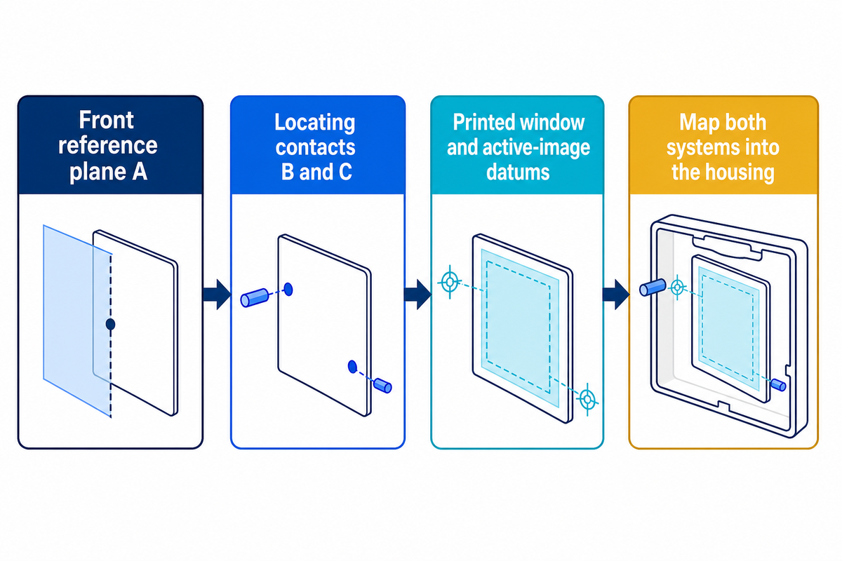
Datums should follow features that locate covers and modules. Establish a front reference plane and in-plane locating features and refer to those throughout glass machining, artwork, module drawings and fixtures. A convenient CAD origin won’t help if the fixture doesn’t contact that feature.
The public ASME dimensioning standard overview describes a common language for expressing design intent. Put the full datum scheme on the controlled drawing; a prose tolerance request can’t establish the same relationships. The cover glass drawing checklist helps organize the drawing package.
Document the role of cover glass as a separate component or a module layer prior to the RFQ.
- Name the installed front reference plane A.
- Identify the in-plane locating features B and C, including their actual contacts.
- Locate the printed window and module active image from their respective datums.
- Show how both datum systems locate in the housing.
Take a hypothetical small batch industrial HMI. The glass inspector reports the printed edge from the left cut edge, the assembler centers the cover between two stops, and the display module installer locates the module from its right mounting feature. All the reports can be correct, yet the origins of the reports don’t describe a continuous chain. The engineer should draw each contact and convert the drawn dimensions to the closing direction. The placement bounds between the contacts should be retained. Paying for more precise print inspection won’t solve undefined module location. The next prototype should use the proposed locating scheme, with both printed-window and active-image measurements reported against the agreed assembly references.
In the illustrative window model, the glass-placement term is 0.10 mm. A datum revision can affect which variation that term represents. Keep physical contacts and signed paths with the calculation to ensure that an artwork or fixture revision does not alter a glass-outline requirement to a different placement requirement.
Check perimeter clearance at the adverse limits
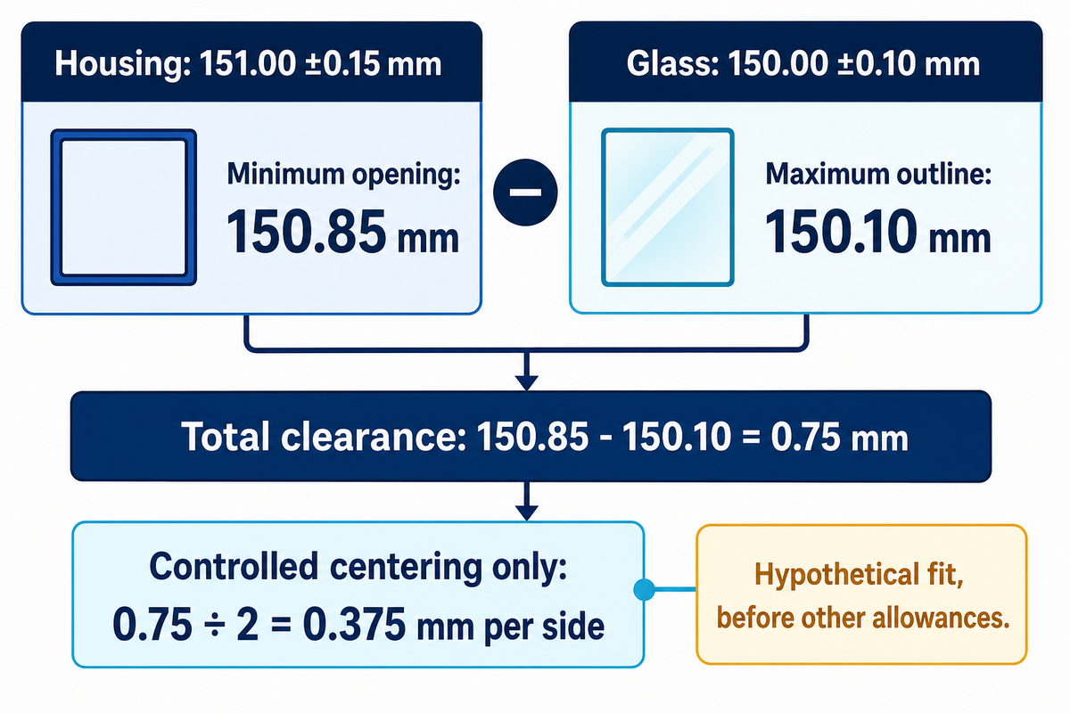
The minimum total perimeter clearance is the smallest housing opening minus the largest finished glass outline along the same axis. A centered per-side result requires controlled centering. For an edge-located or shifted cover, calculate the two gaps separately and include the placement allowance before judging the available clearance.
| Illustrative width | Nominal and tolerance | Adverse limit |
|---|---|---|
| Housing opening | 151.00 ±0.15 mm | 150.85 mm minimum |
| Finished glass outline | 150.00 ±0.10 mm | 150.10 mm maximum |
| Total width clearance | 151.00 − 150.00 = 1.00 mm | 150.85 − 150.10 = 0.75 mm |
| Centered gap before other allowances | One half of the total gap | 0.75 ÷ 2 = 0.375 mm per side |
A width tolerance doesn’t always mean a center position tolerance. An example to support this is Stefan Menin’s 2012 Design World discussion of dimension placement. The calculation must be in accordance with the locating relationships in the drawing.
Common mistake: A common mistake is quoting 0.375 mm as a guaranteed installed edge clearance. Any closure displacement from the centering arrangement consumes that side’s margin. Corner geometry, edge treatment and environmental behavior need to be evaluated independently; use the cover glass hole edge distance guide to evaluate the hole edge distance issue independently.
The 0.75 mm result is total width clearance in a hypothetical planar fit. Only controlled centering divides it into two 0.375 mm gaps. If the buyer needs a minimum clearance on every edge, the drawing must also control placement and any additional movement relevant to the installed condition.
Build the 4-Term Surface-to-Surface Stack Worksheet
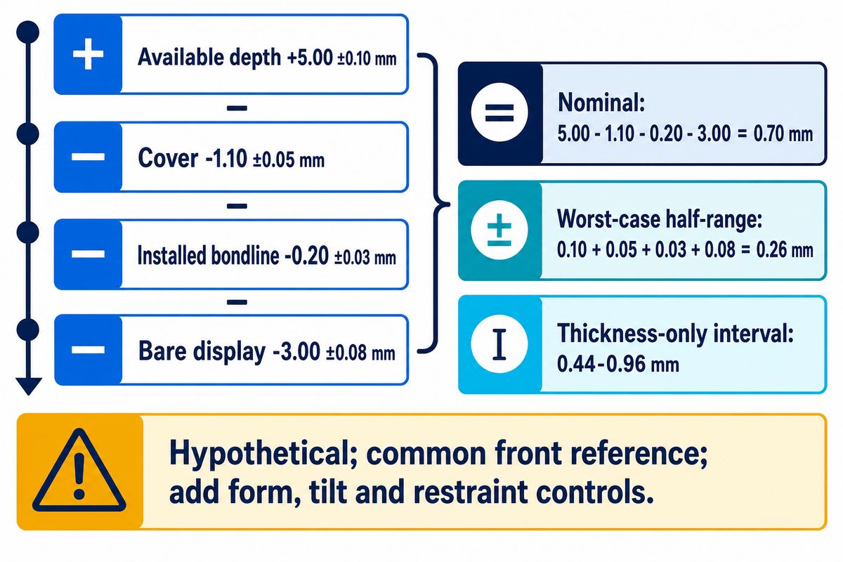
The 4-Term Surface-to-Surface Stack Worksheet removes installed layer thicknesses from a defined depth and allocates each tolerance to its drawing owner. For a display with no cover, include the available-depth, cover, bondline and display terms. Keep the depth reference coincident with the installed cover front face, or include its positioning variation.
| Term and physical endpoints | Sign | Illustrative value | Drawing owner |
|---|---|---|---|
| Available depth: installed cover front reference to rear obstruction | + | 5.00 ±0.10 mm | Housing/assembly engineer |
| Cover: front face to rear face | − | 1.10 ±0.05 mm | Glass drawing owner |
| Installed bondline: glass rear face to display front face | − | 0.20 ±0.03 mm | Bonding process owner |
| Bare display: front face to rear envelope | − | 3.00 ±0.08 mm | Module supplier |
| Nominal rear clearance | Result | 5.00 − 1.10 − 0.20 − 3.00 = 0.70 mm | Assembly engineer |
| Worst-case half-range | Result | 0.10 + 0.05 + 0.03 + 0.08 = 0.26 mm | Assembly engineer |
| Thickness-only clearance interval | Result | 0.44–0.96 mm | Assembly engineer |
The installed adhesive thickness represents the bondline. The removal of a release liner represents no installed depth, while a carrier in the adhesive construction represents some installed depth. For the optical bonding service requirements define compression or cure state.
Take a hypothetical prototype whose installed cover front face coincides with the assembly reference. The housing offers 5.00 mm of depth, and the separate cover, bondline and bare display consume 1.10, 0.20 and 3.00 mm. Nominal clearance is therefore 0.70 mm. At the adverse limits, depth falls to 4.90 mm while those layers increase to 1.15, 0.23 and 3.08 mm: 4.90 − 1.15 − 0.23 − 3.08 = 0.44 mm. The engineer records that result as the thickness-only margin. Before releasing the prototype, the team still checks local surface form and any support-induced movement. An obstruction check must use the installed envelope rather than assume that this positive scalar result proves clearance everywhere.
The public abstract of ISO 10579:2010 on non-rigid parts addresses dimensional verification where restraint is required. A thin cover that is shapeable with support or adhesive may require a local restrained envelope rather than a scalar of thickness. The example does not show that any of the covers in question is non-rigid.
Engineering note
The 0.44 mm minimum applies only to the stated one-dimensional thickness model. Surface form, tilt, restraint and front-reference positioning need additional controls where they affect the gap.
A 0.20 ±0.03 mm installed bondline is an illustrative input, not a tape catalogue specification. Before buying a tighter 1.10 ±0.05 mm cover, confirm the bare-display boundary and local envelope. An uncontrolled support condition can consume clearance that the four scalar dimensions never represented.
Budget the printed window against the active image
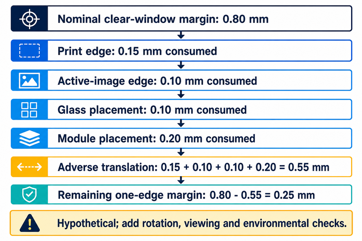
The 4-Term One-Side Window Budget subtracts unfavorable printed-edge, active-image and assembly-placement contributions from the nominal margin on one edge. Express each contribution in the direction of the closing edge as an edge position bound. Convert width and center controls first, then check all four edges without counting the same size variation twice.
| One-edge budget | Illustrative closing contribution | What the input must mean |
|---|---|---|
| Nominal clear-window margin | 0.80 mm available | Margin between the printed boundary and active-image edge |
| Printed edge relative to glass datum | 0.15 mm consumed | Finished print position, with applicable size effects included |
| Active-image edge relative to module datum | 0.10 mm consumed | Module drawing’s active-image location |
| Glass placement in assembly | 0.10 mm consumed | Glass datum to housing location |
| Module placement in assembly | 0.20 mm consumed | Module datum to housing location |
| Total adverse closing movement | 0.55 mm | 0.15 + 0.10 + 0.10 + 0.20 mm |
| Remaining translational margin | 0.25 mm | 0.80 − 0.55 mm, before other allowances |
In Välimäki et al. 2022 printed-electronics study, section 3.4, sensor accuracy is described separately from achieved layer alignment. In that study, the authors use PET rather than cover glass. Therefore, their numerical registration results won’t be a glass specification. Request finished-part print measurements for the silk screen printed glass art.
Suppose a hypothetical narrow-bezel display starts with the 0.80 mm margin in the worksheet. The assembly engineer allocates 0.15 mm to print-edge position, 0.10 mm to the active-image edge and 0.30 mm to the two placement terms. The remaining 0.25 mm hasn’t yet covered rotation or the viewing requirement. Further opening the printed window may reveal an inactive display border, so the designer checks both pixel concealment and unwanted border exposure. The procurement request should identify which edge is being controlled and ask for a prototype under the intended locating scheme. A general promise of precise glass cutting can’t settle the separate print-to-datum and module-to-housing relationships.
For the illustrative edge, 0.55 mm of adverse translation consumes most of the 0.80 mm nominal margin. The remaining 0.25 mm needs separate optical and environmental validation. Use the sunlight-readable display optical bonding guidance when viewing conditions and optical construction also affect acceptance.
Choose worst-case limits or a measured yield model
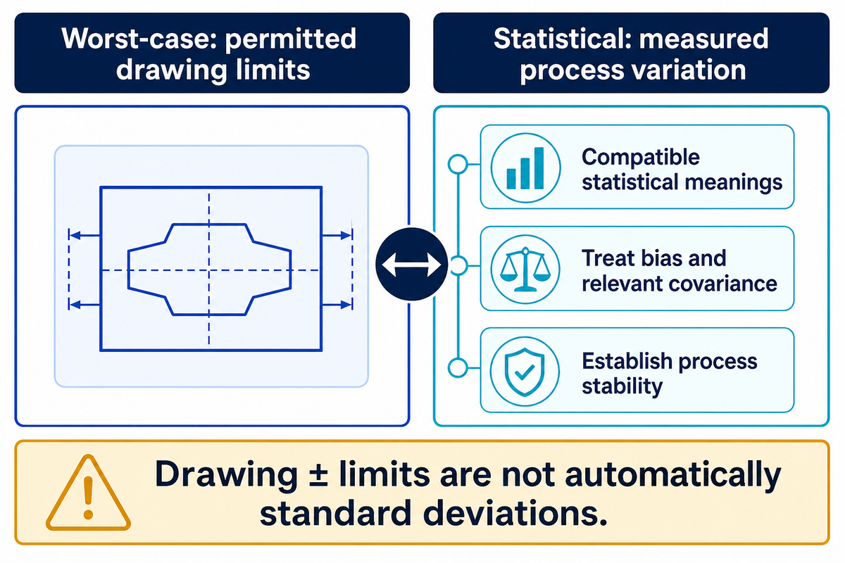
Worst-case tolerance analysis applies an adverse combination of the permitted limits. A statistical approach estimates variability of the population for a given process. Judge the limits themselves using the former. Use the latter only with measured variation, compatible definitions, correlation and bias treatment, plus evidence that the process stays stable over time.
Worst-case limits
Useful for the stated drawing envelope. A positive result still needs all relevant geometric and functional terms.
Measured statistical model
Useful for agreed population-risk decisions. Unsupported distributions or drifting processes invalidate a yield estimate.
NIST’s uncertainty-combination framework includes covariance terms; a simple square-root sum needs the relevant uncorrelated simplification. That metrology framework doesn’t describe a production distribution. NIST’s process-stability framework also accounts for whether the mean, variance and distribution stay the same over time.
If I want to use the RSS method do I just square each tolerance, add them up and take the square root of the sum?
Root sum square is valid only if the quantities being combined have compatible statistical meanings and the model’s assumptions are justified. Arbitrary plus-or-minus limits aren’t automatically standard deviations. Treat bias separately. Include relevant covariance and establish process stability before using a calculated spread to estimate the future assembly yield.
For this illustration, combining the four depth half-ranges by a square-root-of-squares calculation would produce a number smaller than their 0.26 mm sum. The drawings don’t tell us what probability the smaller number represents. Limit checks may be replaced with a population model, but agreement on statistical basis and an accepted escape risk are required.
Common mistake: A fixture offset commonly shared by multiple dimensions is typically treated as unrelated random noise. Analyze how the fixture affects the dimensions and cancellation may occur in some dimensions but not others.
Inspect the finished part under agreed conditions
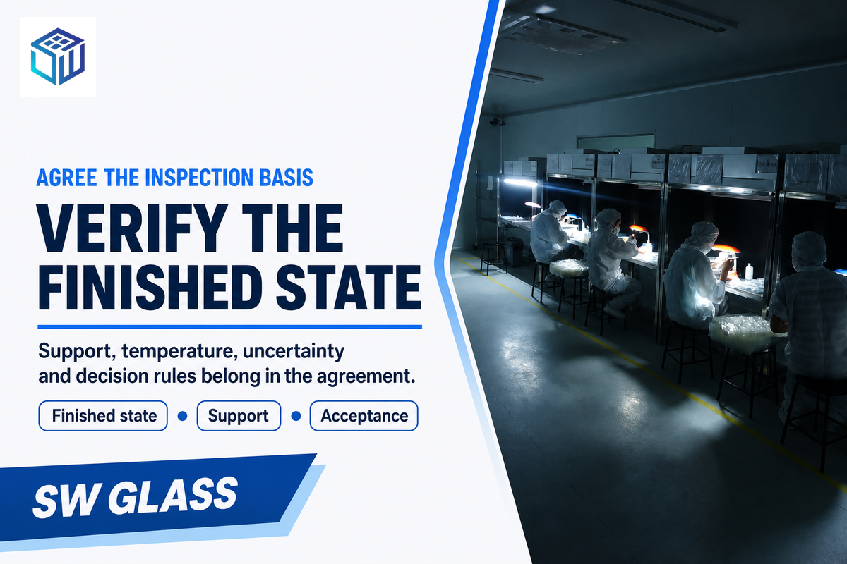
During cover glass inspections, the finished condition of the part must be reproduced. The conditions of support and the datum relationships must also be reproduced. Specify the measurement temperature and uncertainty, then agree how near-limit readings are judged. Size, flatness, print position and material qualification are separate acceptance questions; passing one cannot prove that the assembled display meets the others.
NIST’s study of dimensional measurements at nonstandard temperatures explains temperature-related measurement uncertainty. The public abstract of ISO 14253-1:2017, confirmed in 2023, addresses uncertainty when readings approach specification limits. Agree the decision rule for the contract’s system; the ISO abstract does not automatically impose a rule on an ASME drawing.
| Feature type | Example or required record | Verification and owner | Acceptance limitation |
|---|---|---|---|
| Housing opening | 151.00 ±0.15 mm example | Finished opening; housing quality team | Size alone does not control centering |
| Glass outline | 150.00 ±0.10 mm example | Finished contour; glass quality team | Does not locate the printed edge |
| Cover thickness | 1.10 ±0.05 mm example | Specified locations and support; glass quality team | Does not include local surface form |
| Surface form | Agreed flatness/profile requirement | Free or specified restrained state; assembly engineer | Forceful clamping can change the measured envelope |
| Installed bondline | 0.20 ±0.03 mm example | Installed compression/cure state; bonding owner | Loose tape and removed liners are different states |
| Printed-edge position | 0.15 mm closing bound example | Finished print to datum; glass quality team | Instrument precision is not achieved registration |
| Active-image location | 0.10 mm closing bound example | Module datum to active-image edge; module owner | Module outline size is a different characteristic |
| Assembly placement | 0.10/0.20 mm glass/module bounds | Installed locating features; assembly team | Translation alone does not represent rotation |
| Strengthened-glass classification | Specified material and applicable standard edition | Agreed material report; supplier quality team | Classification does not prove complete-display performance |
Which glass materials can be used for custom display cover glass?
Custom display cover glass needs a specified material family, grade and processing route. Aluminosilicate glass, low-iron glass and other glass options require application-specific qualification. Choosing the right cover glass also includes its finished geometry. A material’s optical clarity or scratch resistance can’t replace the dimensional controls which locate the viewing window.
Record the type of glass, strengthening process and coating with the glass specification. For heat treated tempered glass, include the agreed condition after the heating and cooling process. For chemically strengthened glass, material classification and end use testing remain separate. ASTM’s public scope makes this separation clear.
In the RFQ, specify the type of cover glass to describe the type and condition of each variant. Chemical strengthening requires the material report and a separate acceptance of the application.
“This specification does not purport to address end-use performance.”
Common Mistake: accepting a borderline reading because the displayed digits fall within the limit. Record uncertainty and apply the agreed conformity rule. Withhold an inconclusive result for the defined disposition instead of converting measurement uncertainty to an unearned pass.
An example of a 1.10 ± 0.05 mm thickness requirement needs defined measurement locations and a decision rule. A material certification can’t resolve a near-limit dimensional requirement. Before ordering high-quality glass to that bound, agree how the quality team will report the finished state, uncertainty and any result whose conformity remains unresolved.
Spend tolerance money where the stack changes
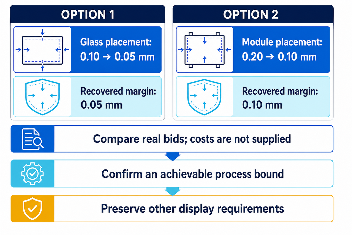
In the case of tolerance allocation, identify which contribution consumes the functional budget first. Compare a glass requirement to the fixture, module and bonding process that affect the same output. Geometric improvement is one input to a purchase decision. Determine the bounds of the processes, and quote the costs to improve, before determining which change is to be implemented.
In the hypothetical window budget, reducing glass placement from 0.10 mm to 0.05 mm recovers 0.05 mm. Reducing module placement from 0.20 mm to 0.10 mm recovers 0.10 mm. Neither comparison proves that tightening the glass cut size changes its placement term.
Armillotta’s 2024 tolerance-optimization research distinguishes feature sensitivity from process-dependent cost. Its mechanical-assembly cost model is not a cover-glass quote. Use the recovered geometric budget to shortlist changes, then compare supplier bids and implementation constraints.
| Contribution | Illustrative bound | First decision and owner | Limit of the decision |
|---|---|---|---|
| Printed-window edge | 0.15 mm closing | Check artwork datum and finished print; glass engineer | Smaller print error does not fix module shift |
| Active-image edge | 0.10 mm closing | Confirm active-image-to-module control; module engineer | Module outline accuracy is not active-image accuracy |
| Glass placement | 0.10 → 0.05 mm | Evaluate locating arrangement; assembly engineer | Recovers 0.05 mm only if the placement bound improves |
| Module placement | 0.20 → 0.10 mm | Evaluate module location; assembly engineer | Recovers 0.10 mm, with no price or yield guarantee |
| Available depth | ±0.10 mm | Check front reference and obstruction; housing engineer | A changed reference adds positional uncertainty |
| Cover thickness | ±0.05 mm | Confirm finished thickness control; glass engineer | Does not resolve unmodeled form or tilt |
| Installed bondline | ±0.03 mm | Review installed-state variation; bonding owner | Catalogue thickness is insufficient |
| Bare-display envelope | ±0.08 mm | Confirm supplied boundary; module engineer | Invalid when a completed module is counted as bare |
| Housing opening | ±0.15 mm | Review minimum opening and contacts; housing engineer | Perimeter improvement does not improve the image-window budget |
When not to buy a blanket tighter glass tolerance
Don’t do a blanket reduction unless the dimensional path has a controlled assembly location. A more precise contour can leave the printed window just as uncertain if artwork registration or module placement dominates. The same objection holds for variability in installed bondline, form of the surface, or an undefined supply boundary. Correct the model and responsible process before turning every drawing dimension into a premium requirement.
A procurement comparison also requires the cost of each proposed change. A revision to a fixture to capture 0.10 mm can require tooling and/or assembly changes, and a glass requirement to capture 0.05 mm can affect fabrication and inspection. The worksheet doesn’t provide costs. Finance compares bids for demonstrated and measurable improvement, and quality assurance confirms the proposed bound is achievable. Impact resistance, touch sensitivity, optical requirements and other changes of the same nature should be grouped together during the review of a purchase order, because a geometric improvement that breaks another display requirement does not qualify as a successful purchasing decision.
Industry Outlook: Recheck the RFQ When Display Construction Changes
A revision to the applicable standard or a changed display construction should be reviewed prior to issuance of the next purchase order. For October 2026, record the applicable standard, the installed geometry, and module revision. Recalculate the functional chain when those inputs change instead of carrying an old positive margin into a new configuration.
The current public page for ASTM C1422/C1422M-26 gives a 2026 chemically strengthened-glass specification. The scope defines the characteristics of strengthening, but not the end-use performance. The version number does not necessarily indicate that a supplier is certified to it, or that a change in dimensional requirements was made. Be sure to check which edition and supporting report apply to the ordered material.
For restrained geometry, the ISO 10579:2010 public page still identifies that edition as current and notes an expected replacement by ISO/DIS 25935. A draft is not a published replacement, and therefore, does not automatically affect an existing contract. Check the applicable document at the time of order release if the project relies on that system for the treatment of non-rigid parts.
The practical construction trigger is also very specific. Changing from a loose, flat cover to a supplied bonded module alters the thickness boundary. Adding other curvatures or changing the locating support can also invalidate a flat scalar envelope. Changing the printed decoration can move the boundary that hides the inactive display border. Each change needs a revised drawing path and application test, rather than an unsupported forecast about the display industry.
- Send the released assembly drawing, glass drawing, artwork and bill of materials with their revisions.
- State the supply boundary and applicable material/process route.
- Attach the depth and four-edge window budgets, including excluded allowances.
- Agree inspection state, uncertainty-aware acceptance and first-article records.
- Assign the review owner for module, fixture, artwork or bondline changes.
Procurement boundary: a supplier cannot guarantee the complete assembly from an isolated glass drawing when the module datum and placement bounds are missing. For the illustrative case of a 0.25 mm remaining window budget, request the missing inputs of the assembly before asking for a guaranteed visible image margin.
Keep a signed revision list with the RFQ. An approved prototype supports the tested construction and conditions; it doesn’t qualify every future display technology or every combination of cover glass materials. Reopen the calculation whenever a change affects a dimension, locating relationship or acceptance criterion.
Frequently Asked Questions
Can you manufacture custom display cover glass from our CAD drawings?
Send released CAD, a dimensioned drawing and controlled artwork; the quote needs the finished-part requirements.
CAD identifies the shape, but it rarely captures every acceptance condition by itself. Include the outline, holes, thickness, printed window, datum references and any critical finished-state dimensions. Specify material and processing, then identify which component supplier owns each measurement. If the cover must fit a supplied module, include the module drawing and assembly locating scheme. A custom display quote should state deviations or unresolved inputs before order release. The complete display fit remains an assembly requirement rather than a promise inferred from one component file.
What is the difference between tempered glass and Gorilla Glass?
Tempered glass names a processing category; Gorilla Glass is a branded glass family that needs an exact product specification.
Do not use a brand name as a substitute for a material grade or strengthening route. Thermally tempered glass is heat-treated, while the order for a branded glass product must identify the manufacturer’s grade and supplied condition. The material choice can affect durability, scratch resistance and display performance, but those properties need their own qualification. ASTM C1422/C1422M addresses chemically strengthened-glass classification and expressly excludes end-use performance. Ask for the applicable material report and application tests, then verify finished dimensions under the agreed support condition. A change between different glass types also requires a review of the coating and bonding construction before assuming that the original clearance budget still applies.
What glass thicknesses are available?
Availability depends on the specified material, product and processing route; obtain a current supplier confirmation.
The hypothetical 1.10 mm cover in the worksheet is an arithmetic input, not a stock-thickness catalogue. Ask for the nominal glass thickness, achievable finished tolerance and measurement locations for the selected grade. A thicker cover changes the installed stack and can affect touch performance, so module and bonding compatibility need review. Don’t infer a universal thickness range from one example or from standard glass offered for another application.
Thicker glass may change the assembly depth requirement; qualification of glass performance is still needed with the supplied module.
What should I consider when selecting cover glass for outdoor displays?
Review environmental movement, viewing conditions, surface treatments and the complete installed display.
Outdoor cover glass applications need more than a room-condition fit check. Define the operating environment and test whether relative movement consumes the mechanical or image-window margin. Evaluate glare, reflection and light transmission with the intended coating and optical construction. The choice of cover glass also affects user experience and touch sensitivity, which belong in application testing. Neither the 0.44 mm depth result nor the 0.25 mm one-edge margin proves outdoor performance. Before selecting cover glass, agree the conditions under which display quality and mechanical acceptance must both be maintained.
How do I maintain my cover glass?
Use cleaning materials compatible with the specified surface treatment and inspect damage against the agreed acceptance criteria.
A scratch or damaged edge needs assessment against the component requirements. Avoid assuming that every cleaner suits every glass surface or coating. Obtain the care instructions for the supplied finished product.
Comparing different types of cover glass requires consideration of their specified surface treatments. Changes for aesthetic appeal, such as a wider printed border, require the same active-image clearance check.
Request a drawing-based quotation
For a custom cover glass enquiry, send the released drawings and artwork with the required finished-state measurements. Ask SW Glass to quote the glass controls it supplies, while the module and assembly owners confirm their contributions to the complete stack.
Method and evidence: the engineering examples (worksheets) are hypothetical and not based on customer case histories, supplier process-capability data, or design/manufacturing limits. The standards references are to descriptions and scopes of the documents reviewed in October 2026. Qualification remains application-specific.
Related Articles
References & Sources
- Y14.5 Dimensioning and Tolerancing, American Society of Mechanical Engineers; 2018 edition, reaffirmed 2024; public overview.
- Why it’s important to always use tolerances, Stefan Menin, Design World, 2012; dimensional-chain method.
- ISO 10579:2010, Dimensioning and tolerancing: Non-rigid parts, International Organization for Standardization; public abstract and current/draft status.
- Välimäki and colleagues’ printed-electronics alignment study, The International Journal of Advanced Manufacturing Technology, 2022; section 3.4.
- Combining uncertainty components, National Institute of Standards and Technology; covariance-aware propagation.
- Assessing Process Stability, section 3.4.5, National Institute of Standards and Technology Engineering Statistics Handbook.
- Uncertainties in Dimensional Measurements Made at Nonstandard Temperatures, Dennis A. Swyt, National Institute of Standards and Technology.
- ISO 14253-1:2017, Decision rules for verifying conformity or nonconformity with specifications, International Organization for Standardization; public abstract, confirmed 2023.
- C1422/C1422M-26, Standard Specification for Chemically Strengthened Flat Glass, ASTM International, 2026; public Scope 1.2.
- Estimation of cost reduction by tolerance optimization, Antonio Armillotta, The International Journal of Advanced Manufacturing Technology, 2024; sections 6–7.