Get in Touch with Saiweiglass


Vehicle Touchscreen Engineering Guide: Stack, Validation, and RFQ

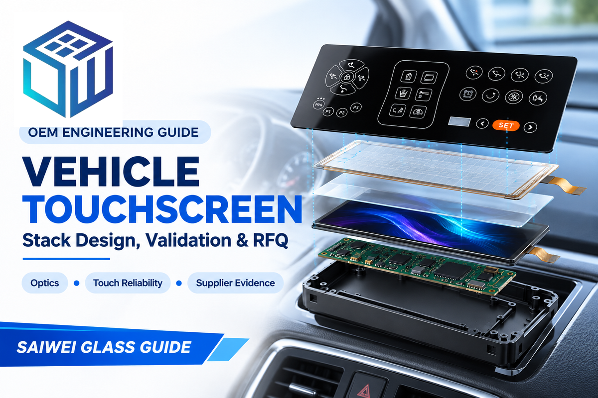
OEM Engineering Guide
A touchscreen is more than a display with a touch layer. It’s a stack of optical, electrical, mechanical, and surface systems. If those layers are specified independently, a sample can look acceptable on a bench yet suffer glare, false touches, dead zones, bubbles, or edge stress after installation.
This guide helps automotive engineers, quality teams, and procurement managers define the complete assembly, plan meaningful validation, isolate failures, and request comparable supplier evidence.
What a Vehicle Touchscreen Includes Beyond the Visible Display
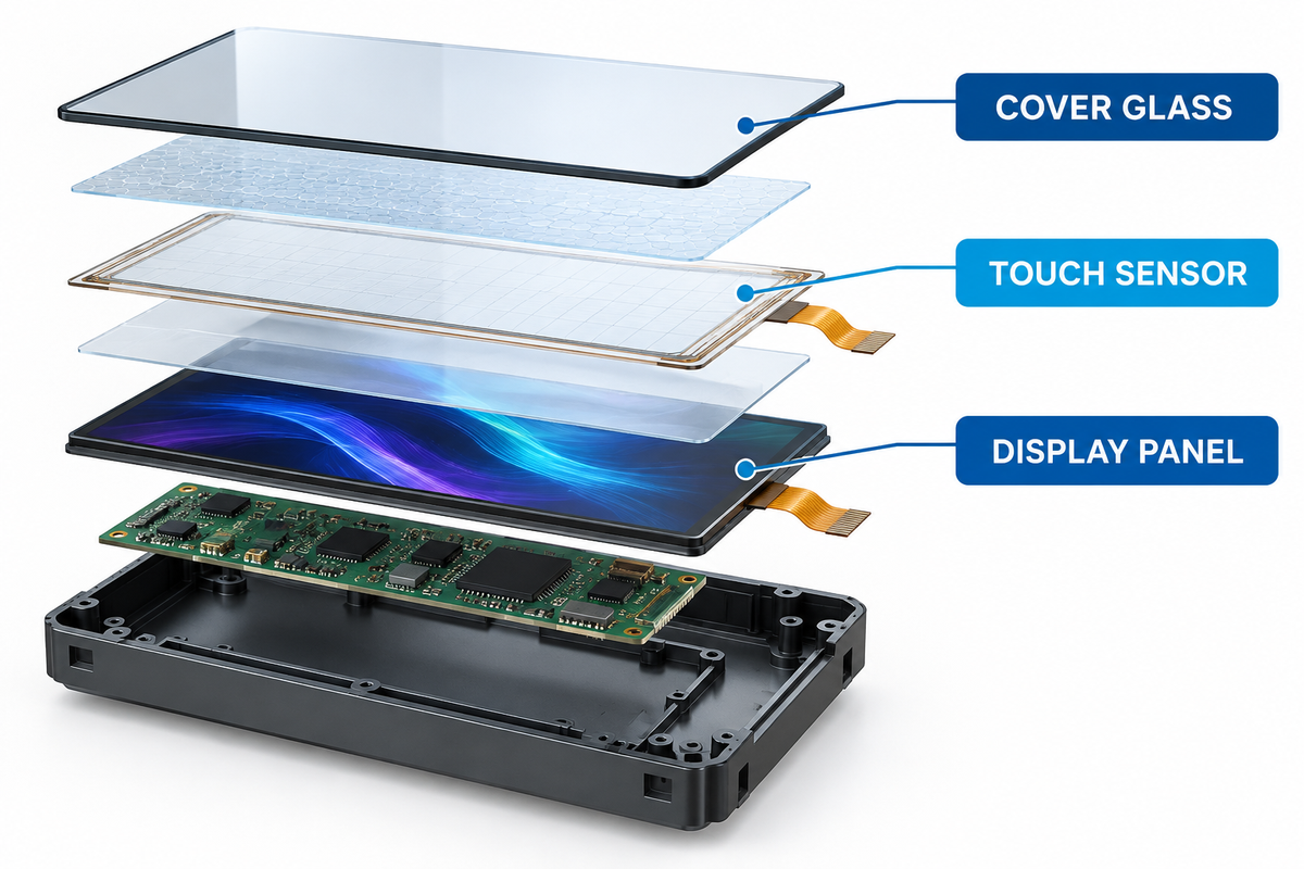
The useful engineering unit is the stack as a whole. Capacitive sensor systems are typically designed to function with a cover lens as part of the system, to absorb shock, and to maintain a defined spacing from touch surfaces. The cover lens adds a layer of protection, while the geometry and enclosure of the car’s dashboard and the wider vehicle determine mechanical loads and reflective light paths. A projected capacitive touch sensor may work well by itself, while the installed system underperforms because the cover lens is thicker, the adhesive changes the optical path, the enclosure introduces stress, or electrical noise reduces touch margin.
The Seven-Layer Stack
| Layer | Primary job | Evidence to request | Typical risk |
|---|---|---|---|
| Surface treatment | Control reflection, glare, smudges, and finger feel | Method, condition, durability result, approved cleaner | Haze, sparkle, wear, friction change |
| Cover lens | Protect and define the visible interface | Material, thickness, strengthening, edge and print drawing | Crack, warp, cosmetic defect, weak edge |
| Touch sensor | Detect fingers, gloves, gestures, and multiple touches | Sensor structure, active area, routing, raw data | Dead zone, coordinate error, weak signal |
| Bonding layer | Join optical surfaces and manage reflections | Adhesive, thickness, cure route, bubble criteria | Bubble, delamination, yellowing, stress |
| Display panel | Create the image | Luminance, contrast, color, viewing-angle method | Washout, mura, image retention, thermal drift |
| Touch controller | Scan, filter noise, calculate coordinates, report faults | Part and firmware revision, tuning file, diagnostics | False touch, latency, reset, noisy coordinates |
| Mechanical and vehicle integration | Support the stack and connect it to the host | Housing, bezel, grounding, cable, connector, mounting loads | Edge stress, electromagnetic coupling, connector fatigue |
Keep one controlled drawing of the stack during revision. Separate part approvals don’t constitute approvals for interaction.
Choose the Stack Around the Operating Environment
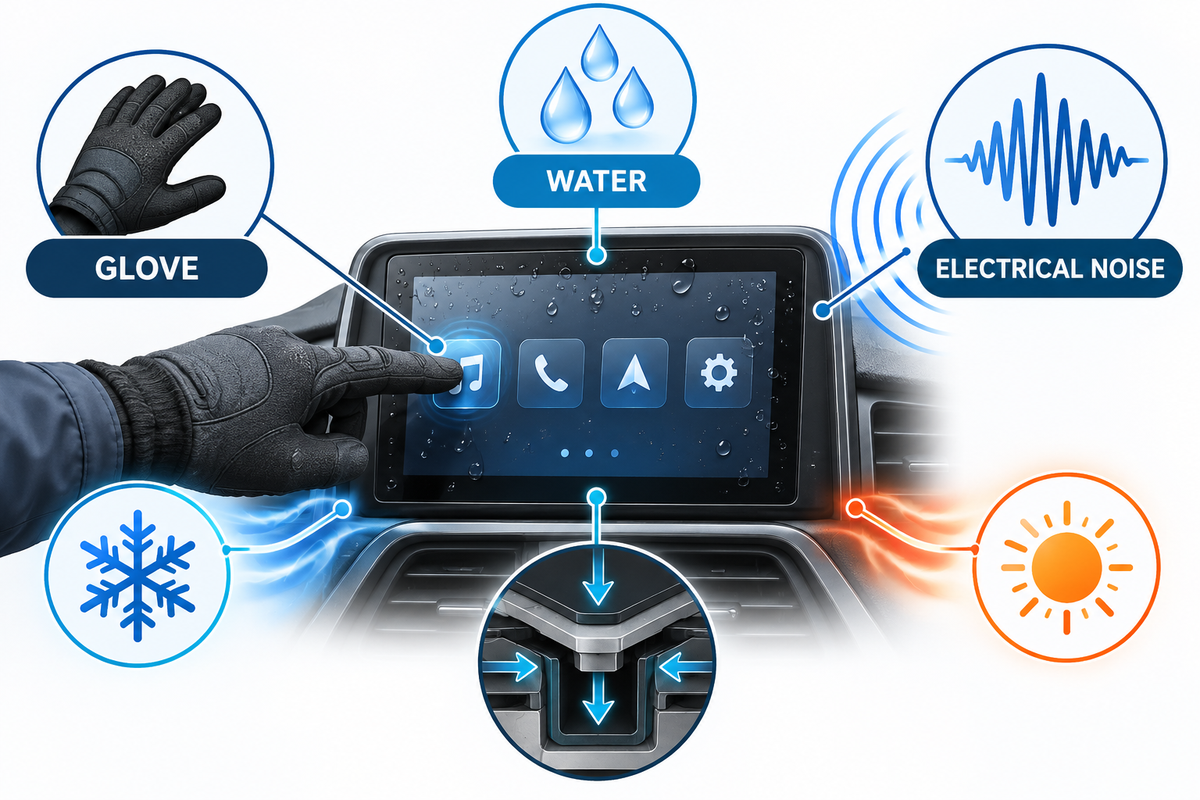
The starting point for a new design should be the use case. That includes screen location, viewing angle, the environments in which it’s used (sun, water, dust, oils, greases, solvents, fuels, EMI, RFI), vibration, shock, temperature, fatigue life, service life, and cleaning. The last becomes especially important if the system is mounted on the vehicle.
An OEM infotainment system may place a large display in the center console, but screen size and display area do not define reliability. The touchscreen display still has to support the intended user experience and driving experience without hiding critical feedback. An automaker may combine information and entertainment, an audio system, climate control, and vehicle-to-vehicle information in the same in-car interface, so the validation boundary must cover that wide range of functions and the interaction among the various systems.
Thick cover lenses, gloves, moisture, and electromagnetic noise are automotive touch challenges, per Microchip. Similarly, Infineon lists thick-overlay, glove, water-rejection, and wet-finger functions for automotive controller families. These are functional categories, not guarantees, for an arbitrary assembly. The final lens, sensor geometry, adhesive, grounding, enclosure, and water condition, together with firmware and the vehicle’s electronics, still require representative-stack testing.
Why more sensitivity is not automatically safer
Increasing sensitivity may recover a weak touch signal through a thicker lens, but it could also reduce the margin against water, noise, or unintended contact. A requirement that defines both the intended event and the unacceptable event would be useful. For example: detect a specified gloved finger at defined locations, while rejecting droplets and avoiding false commands during the agreed electrical-noise exposure.
Controller qualification covers the controller, not the complete screen or vehicle. Wiring-loom routing, grounding, bezel material, nearby antennas, power converters, and display electronics can change electromagnetic behavior. The installed assembly therefore needs emissions and immunity evidence tied to its final revision.
Keep hardware reliability separate from driver-task suitability. The NHTSA driver-distraction guidelines are voluntary and nonbinding. They evaluate visual-manual secondary tasks on original-equipment devices. That is a different question from touch-stack performance. Euro NCAP’s 2026 protocol rewards direct physical input for specified basic driving controls. A low control score does not by itself prevent a five-star overall rating. Define which functions belong on the touchscreen, who may use them, and under which vehicle state before validating the hardware.
Optical Performance: Readability Is a System Result
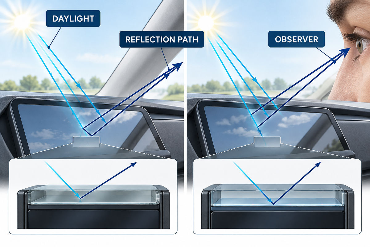
There are other factors besides panel luminance. An ultra-bright display can reflect the cabin or the sky if there’s a large air-gap, or if the display cover has a textured anti-glare finish. A display can shift contrast and color based on viewing angle.
SAE J1757/1 focuses on measuring vehicular displays under automotive ambient light conditions, with an emphasis on high contrast ratio. The standard doesn’t set universal automotive compliance thresholds. Use its metrology principles to define a reproducible method, then set program-specific conditions and acceptance limits. The 2021 revision doesn’t resolve all the use cases including polarized-sunglasses behavior.
| Treatment | What it changes | Trade-off to verify |
|---|---|---|
| Anti-glare | Redistributes specular reflections | Haze, sparkle, text sharpness, finger feel |
| Anti-reflective | Reduces reflection at selected optical interfaces | Coating durability, color shift, cleaning compatibility |
| Anti-fingerprint | Changes oil wetting, cleanability, and surface friction | Abrasion life, cleaner resistance, touch feel |
| Optical bonding | Removes an air interface and stabilizes the stack | Adhesive aging, bubbles, stress, repair strategy |
Measure the same finished construction that will enter the vehicle. A coating coupon or unbonded display cannot represent the final optical path.
The Touch-Reliability Bottleneck Map
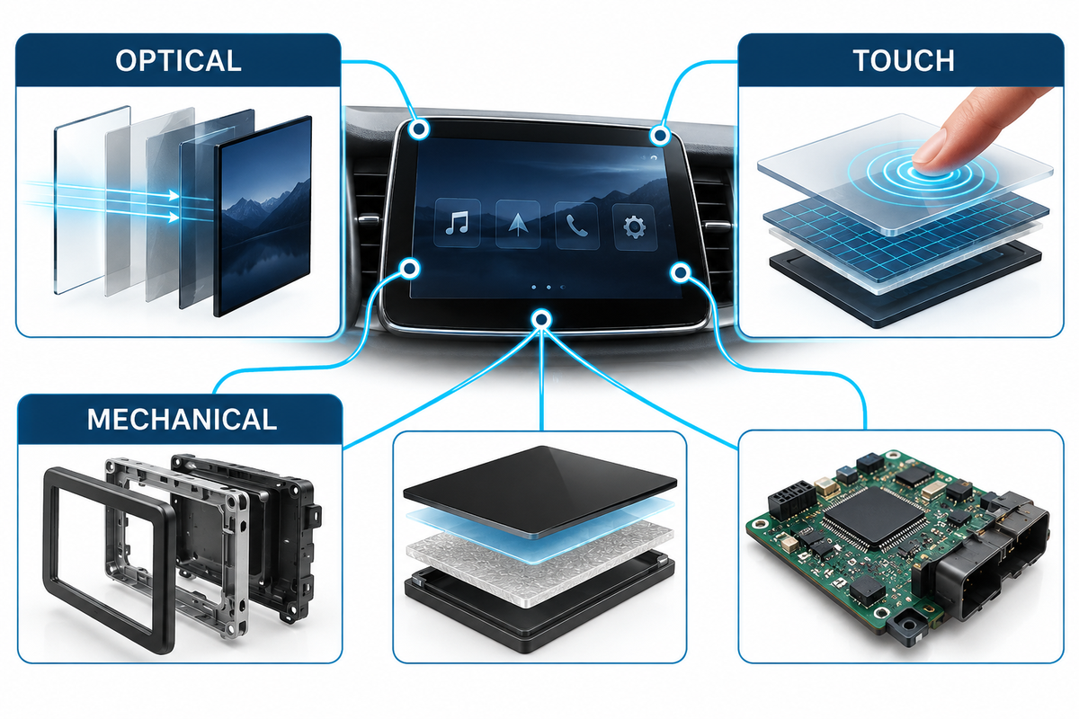
This map prevents a common program error: assigning a symptom to the most visible component instead of the layer that produced it.
| Observed risk | Hidden bottleneck | Next discriminating evidence | Typical owner (project-defined) |
|---|---|---|---|
| Gloved touches are missed | Signal margin through the approved overlay | Raw signal and noise by location with the specified glove | Touch engineering |
| Rain causes commands | Water classification and grounding | Event log during defined droplet and film tests | Controller and vehicle electronics |
| Screen reads well in a lab but not in the car | Installed reflections and viewing geometry | Ambient-contrast measurement on the final stack and bezel | Optical and cockpit integration |
| Bubbles appear after heat and humidity | Adhesive, cure, contamination, or expansion mismatch | Cross-section, cure record, pre/post image and adhesion evidence | Bonding process and quality |
| Edges crack after mounting | Edge strength and enclosure load path | Fractography, flatness, torque, support and tolerance-stack review | Mechanical engineering |
| Coordinates jump near a power event | Power, grounding, electromagnetic coupling, or tuning | Synchronized raw touch, rail, bus, and interference logs | Electronics and software |
For quality teams, the major advantage is faster containment. For procurement, it prevents suppliers from passing the buck across interfaces. For finance and program management, it lessens unwanted late tooling changes and repeated vehicle trials.
Validation Plan Before Tooling and PPAP
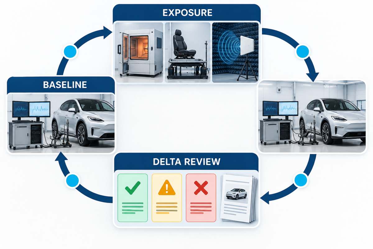
A project-specific test list is required because vehicles’ locations, stacks, and acceptance limits differ. The program needs to translate vehicle operating conditions into test methods, test conditions, sample requirements, and acceptance criteria. Production Part Approval Process documentation should then reflect the customer-specific part, process, and evidence package.
The Validation Delta Protocol
- Freeze the specimen: record drawing, bill of materials, lens, treatments, sensor, adhesive, display, controller, firmware, enclosure, cable, and fixture revisions.
- Define the method: indicate instruments, calibration, lighting, angle, temperature, recovery period, touch target, glove, water, electrical state, and operator rules.
- Capture the baseline: measure optical output, reflection-related metrics, raw touch signal and noise, accuracy, latency, false and missed events, electrical behavior, dimensions, and visible condition.
- Apply the exposure using the program’s thermal, humidity, vibration, impact, ultraviolet, chemical, abrasion, electrostatic-discharge, and electromagnetic conditions.
- Repeat the same measurements; do not replace a numerical baseline with a visual “works” check.
- Classify every delta as immediate failure, recovered behavior, drift, cosmetic change, intermittent event, or no observed change.
- Close the evidence loop by assigning containment, root cause, corrective action, revalidation scope, retained sample, lot traceability, and change-notification rule.
A passed component test is not a passed vehicle touchscreen. Approval belongs to the identified stack, method, condition, limit, sample set, and revision.
Diagnose Common Vehicle Touchscreen Failures by Layer
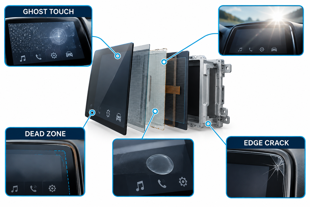
False or ghost touch: Inspect sensor raw data, command logs, and water state. Check grounding and power rails. Investigate exposure to EMI. If the raw signal is stable but the reported command is wrong, inspect controller configuration, coordinate mapping, host communication, and software.
Dead zone or poor edge response: check sensor routing, bond uniformity, enclosure proximity, local air gaps, edge geometry, and tuning by coordinate. A global sensitivity change can hide the symptom while weakening noise rejection elsewhere.
Slow Response: consider system latency in the overall chain including sensing, control, communication, and feedback.
Glare or washout: reproduce the observer geometry and the illumination conditions, reflectance, contrast, haze, and sparkle. Record surface reflection, ambient contrast, haze or sparkle, display output, content state, temperature, and eyewear condition.
Bubbles or delamination: Compare the failure position to adhesive flow, cure, cleanliness, print steps, edge seal, thermal expansion, humidity exposure, and mechanical loads.
Coating wear or edge cracking: Review the approved cleaner, abrasion, coating sequence, edge finish, strengthening sequence, handling/mounting fixtures, flatness, and torque applied.
RFQ Scorecard for a Custom Vehicle Touchscreen
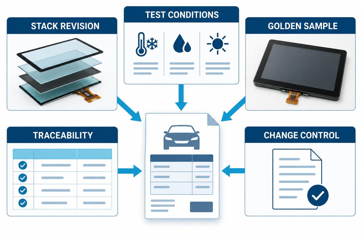
An evidence ready quotation brings suppliers into the same framework. Give each line a method, condition, project limit, sample requirement, responsible revision, and evidence deliverable.
| RFQ category | Required fields | Evidence at sample stage | Evidence before production |
|---|---|---|---|
| Supply boundary | Cover, sensor, bonding, display, controller, cable, enclosure | Controlled stack drawing | Approved bill and revision record |
| Mechanical | Size, thickness, visible area, edge, flatness, print, mounting | Dimensional report and fixture method | Capability and inspection plan |
| Optical | Lighting, angle, temperature, state, method, limit | Sample-level results on the full stack | Lot-control method and change rule |
| Touch | Finger, glove, water, locations, gestures, latency, false events | Raw and reported data with tuning revision | End-of-line coverage and firmware control |
| Environment | Exposure profile, fixture, operating state, recovery, remeasurement | Validation Delta Protocol report | Approved validation matrix |
| Quality | Cosmetic zones, sampling, traceability, retained samples | Golden sample and defect catalogue | Control plan and lot records |
| Change control | Material, process, site, equipment, software, sub-tier changes | Proposed notification route | Contracted approval and revalidation rule |
| Driver-task allocation | Function, user, moving or parked state, fallback control | Task map and interaction rationale | Approved HMI and market-rating evidence |
| Service strategy | Replaceable boundary, calibration, diagnostics, repair access | Service concept and fault-readout sample | Approved service instruction and spare-part rule |
When moving from engineering education to supplier talk, the project is ready to use the automotive display capabilities page, along with this scorecard. Related stack decisions can be scoped through Saiwei’s pages for custom touch screen glass, optical bonding, chemically strengthened glass, and the guide to AG, AR, and AF coating choices.
What Saiwei Glass Needs Before Quoting
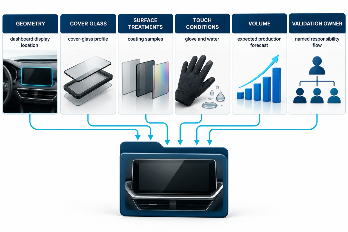
Complete the latest drawing and specify the display location, visible and active areas, cover-lens material and thickness, strengthening, edge and print requirements, surface treatments, bonding boundary, touch structure and control, optical conditions, glove and water conditions, temperature, expected volume, validation responsibilities, and required traceability.
Saiwei Glass presents cover-glass, surface-treatment, touch-panel, bonding, and display-integration capabilities on its first-party automotive page. Treat published figures as supplier-stated capabilities that must be confirmed for the project. Don’t presume that a component qualification, or a catalogue maximum, becomes a guaranteed performance of the finished assembly.
Frequently Asked Questions
What is the difference between a vehicle touchscreen and the display behind it?
The display creates the image, and the touchscreen generates the input. The construction of an automotive assembly depends on the cover lens, treatments, touch sensor, air gap or adhesive, display panel, controller, and housing. A responsive sensor cannot compensate for glare, mechanical stress, electrical noise, or a poorly controlled bonded stack, so the complete assembly needs one specification and validation plan.
How do engineers make an automotive touchscreen work with gloves or water?
They calibrate the projected capacitive sensor and controller to the actual lens thickness, type of glove, condition of water, grounding, electromagnetic environment, and the gestures to be detected. Increased sensitivity can also lead to an increased number of false events. The test plan should reproduce the installed stack and define both successful inputs and forbidden inputs under dry, wet, gloved, and electrically noisy conditions.
Which tests should be completed before vehicle touchscreen tooling and PPAP?
The plan is project-specific, but it should begin with optical, touch, electrical, cosmetic, dimensional, and mechanical baselines. Samples then receive the agreed environmental, vibration, impact, chemical, wear, electrostatic-discharge, and electromagnetic exposures. Repeat the same measurements, review deltas by layer, approve the identified stack revision, and define traceability and change-notification evidence before production approval.
Anti-glare redistributes reflected light, anti-reflective reduces selected reflections, and anti-fingerprint changes surface cleanability and finger glide.
Anti-glare redistributes reflected light, anti-reflective reduces selected reflections, and anti-fingerprint changes surface cleanability and finger glide. Their effects interact with haze, sparkle, image contrast, durability, bonding, and cleaning chemicals. Select them relative to the requirements of the optical system rather than treating them as equivalent.
What information belongs in a custom vehicle touchscreen RFQ?
Include the drawing revision, stack construction, cover-lens material and thickness, edge and printing requirements, surface treatments, optical measurement conditions, touch scenarios, environmental exposures, cosmetic zones, sampling, traceability, golden samples, change control, required evidence, and project limits.
References & Sources
- SAE J1757/1: Standard Metrology for Vehicular Displays
- Microchip Automotive Touch
- Microchip: Touchscreen Controllers for Automotive Displays
- Infineon Automotive Multitouch
- NHTSA Visual-Manual Driver Distraction Guidelines
- Euro NCAP 2026 Basic-Control Testing Note
- ISO 26262 Road Vehicles Functional Safety
- IEC CISPR 25:2021 Scope